Schematic
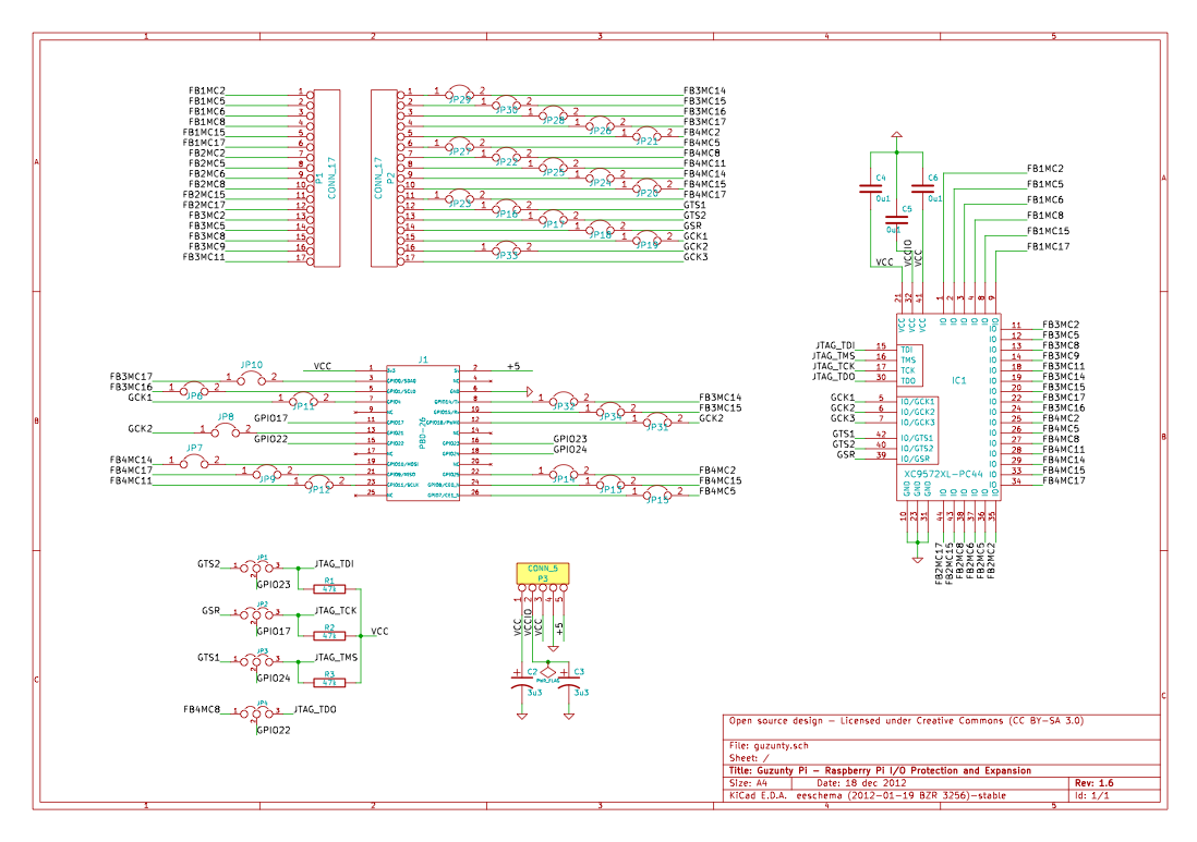
The Guzunty board schematic. A pdf version of this is available in the repository.
The following links are normally closed on the board:
JP7, JP9, JP11, JP12, JP13
JP21, JP26, JP28, JP29, JP30, JP33
All others are delivered normally open. Normally closed links may be opened by cutting the link between the pads with a modelling knife. Normally open links may be closed with a blob of solder. These changes are reversible for a limited number of cycles (limited by the heat tolerance of the PCB substrate and copper layer).
Please note the license terms, CC BY-SA 3.0. For more details please see this page. You may use this work freely under the terms of this license provided you provide attribution and a link back to the home page of this wiki from your distribution site and in any source code or hardware design files you distribute which is based on this work.