-
Notifications
You must be signed in to change notification settings - Fork 85
Sensors and Actuators
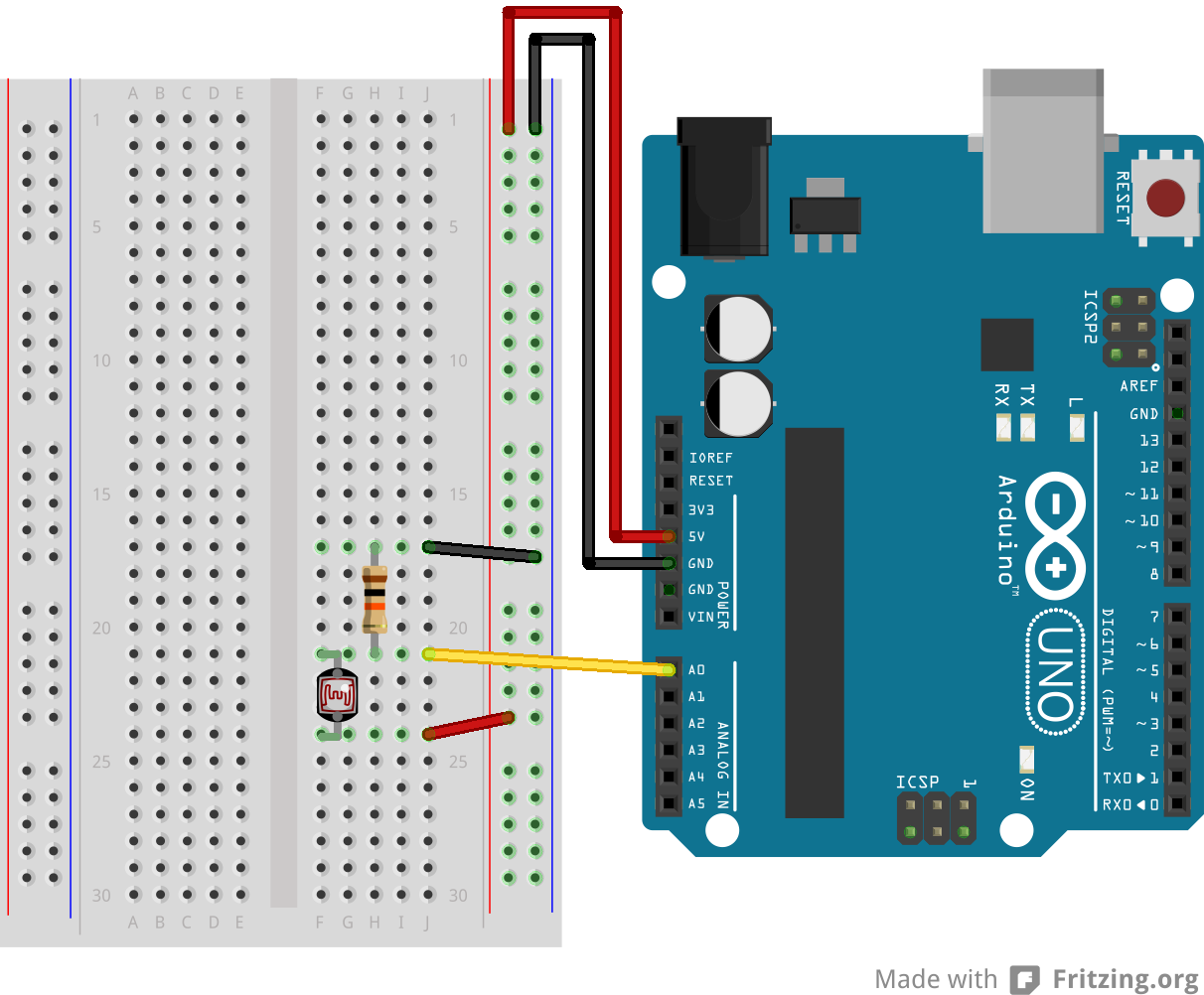
For a regular analog or digital sensor, wire its 5v and GND (ground) pins into the Arduino's corresponding pins, and the device's Signal into a digital (3 to 12, usually) or analog (A0 to A5, usually) pin in the Arduino. Some sensors will require that you put together a simple circuit composed of resistors or capacitors, please read the manufacturer's documentation carefully. Examples of sensors requiring special circuitry are photoresistors (light sensors, or LDRs) or push buttons.
For a specific, more complex device, like an ultrasound distance sensor or a Nunchuck controller, please head over to Firmata Modifications to see if there is a way to use it in Snap4Arduino.
Please follow this wiring diagram to read values from a push button:
You need to build a simple voltage divider to get readings from these sensors. Please follow this wiring diagram:

For a regular digital or PWM actuator, wire its 5v and GND (ground) pins into the Arduino's corresponding pins, and the device's Signal into a digital (3 to 12, usually) or PWM (indicated by the ~ symbol) pin in the Arduino. Some actuators will require that you put together a simple circuit composed of resistors or capacitors, please read the manufacturer's documentation carefully.
For a specific, more complex device, like a stepper motor or an LCD screen, please head over to Firmata Modifications to see if there is a way to use it in Snap4Arduino.
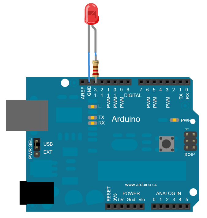
LEDs shouldn't be connected into digital outputs without passing through a resistor. Here's a diagram showing you how to do so:

If you fail to use resistors, you may shorten the life of your LED and may even burn it.
If you don't have any resistors, you can always connect LEDs directly to pin 13, as this special pin comes with an internal resistor.
Connect its 5v and GND pins into the Arduino corresponding pins, and the signal pin into one of the servo-enabled pins in your board. You can check the ones your board supports by checking the drop down menu of the servo block in Snap4Arduino:
You can now use this very block to control your motor. If you are using a continuous rotation servo, you can use the provided clockwise, counter-clockwise, stopped and disconnected options from the second drop down menu. If your servo is an angle-positionable one, just input the angle in degrees into the block.
Regular DC motors run on regular 5v so, theoretically, you could just plug one of the terminals into a ground pin and the other one into a regular digital output. However, these draw quite a bit of current on startup and they may cause your board to reset, and with this simple setup there's no way to prevent current from flowing back to the board and they offer no possibility of changing the motor's direction.
What's usually advised is to use an H-bridge, which is a very simple circuit that takes care of all these. You can find them for a few Euros in any electronics store or online.
Many H-Bridges allow you to drive two motors at the same time, using up two different digital pins for each motor.
--
All wiring diagrams made with Fritzing and extracted from the Arduino.cc site

