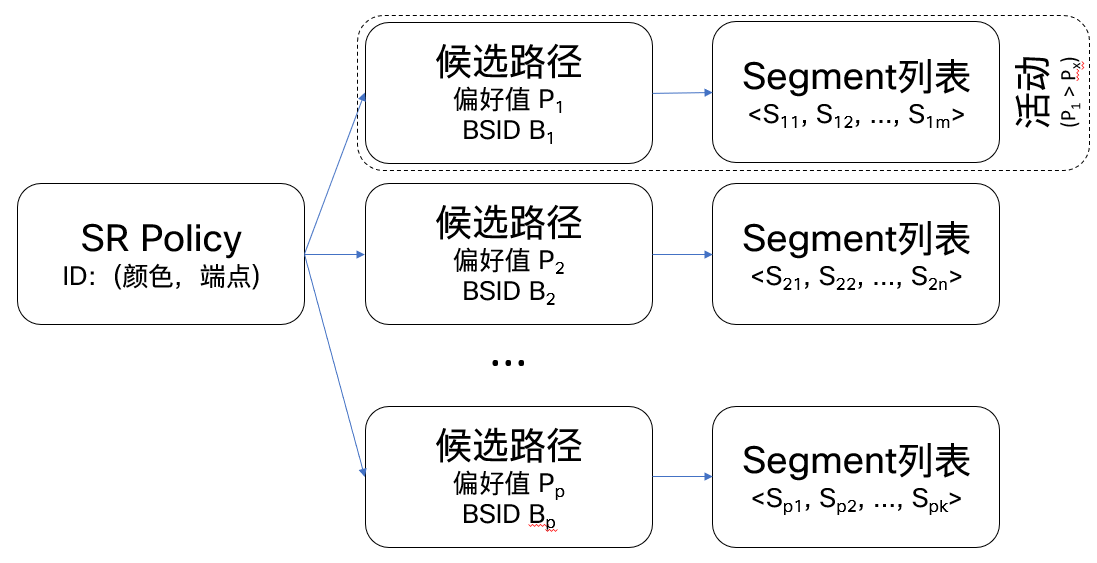
SR其中一个关键功能是SR-TE。SR-TE将用户的意图(延迟、不相交路径、SRLG、带宽等)转换为Segment列表(每个Segment代表特定的操作,Segment列表是指这些Segment的有序列表),然后将Segment列表编程到单域/跨域网络的边缘设备上,同时引导流量至Segment列表所对应的路径上,从而实现“基于意图的网络(IBN)”,完成传统网络向下一代网络平台的演进。 对于简单的SR-TE功能,基于隧道接口体系实现起来比较简单,在SR-TE的导入期,能满足大多数用户的需要。其引流方式也沿用RSVP-TE的方式,用户也比较习惯。
但是,也正是由于隧道接口体系继承了RSVP-TE的实现,使得这种体系下的SR-TE实现存在着明显不足:
- 隧道接口和引流两者是分开实现的,引流方式往往非常麻烦且造成性能损失;
- 往往需要预先配置隧道,在无法明确隧道终点的情况下,只能是部署全网状的隧道,造成可扩展性问题;
- 绝大多数厂商在沿用隧道接口体系的同时,也沿用了RSVP-TE的电路算法[2],表现为只能用Adj-SID编码路径,而无法使用Prefix-SID编码路径,导致无法利用IP ECMP的能力,并且造成Segment列表长度过长,容易超出一些低端设备的支持能力;
- 隧道与路径一对一的关系,因此要配置多个隧道接口用于实现在多条路径上的(等价/不等价)负载均衡,配置繁琐且影响扩展性;
- 隧道接口占用了设备上的逻辑资源,使得设备能支持的SR-TE数量有限
- 不支持一些新的SR功能例如灵活算法(Flex-Algo)、性能测量(Performance Measurement)等
SR Policy完全抛弃了隧道接口的概念,是重新设计的一套SR-TE体系。
SR Policy通过解决方案Segment列表来实现流量工程意图。Segment列表对数据包在网络中的任意转发路径进行编码。列表中的Segment可以是任何类型:IGP Segment、IGP Flex-Algo Segment、BGP Segment等。
SR Policy由以下三元组标识:
- 头端(Headend):SR Policy生成/实现的地方;
- 颜色(Color):是任意的32位数值,用于区分同一头端和端点对之间的多条SR Policy;
- 端点(Endpoint):SR Policy的终结点,是一个IPv4/IPv6地址。
关于SR Policy的细节,可以参考SR Policy
我们目前使用的IOS image还不支持SR Policy,所以这儿只能用SR-TE policy来做segment router traffic引流实验。 在前面的步骤中,我们已经搭建好了一个Segment Routing的网络,从router 2到router 5有2条路径,所以在这一步中,我们来创建2个SR-TE policy分别代表这2条路径。
- router 2 配置 在这里指定了2条路: router2 - router3 - router5走prefix-sid label 16300和16510. router2 - router4 - router5走prefix-sid label 16400和16510.
explicit-path name path_2_3_5
 index 1 next-label 16300
 index 2 next-label 16510
!
explicit-path name path_2_4_5
 index 1 next-label 16400
 index 2 next-label 16510
!
再配置2个tunnel:
interface tunnel-te1
 ipv4 unnumbered Loopback0
 autoroute announce
 !
 destination 192.168.100.10
 path-protection
 path-option 10 explicit name path_2_3_5 segment-routing
!
interface tunnel-te2
 ipv4 unnumbered Loopback0
 autoroute announce
 !
 destination 192.168.100.10
 path-protection
 path-option 1 explicit name path_2_4_5 segment-routing
!
配置完后我们来查看tunnel的状态
RP/0/0/CPU0:ios#show mpls traffic-eng tunnels brief
Thu Nov 14 07:30:57.816 UTC

                     TUNNEL NAME         DESTINATION      STATUS  STATE
                      tunnel-te1      192.168.100.10          down  down
                      tunnel-te2      192.168.100.10          down  down


RP/0/0/CPU0:ios#show mpls traffic-eng tunnels detail
Thu Nov 14 07:31:54.612 UTC


Name: tunnel-te1  Destination: 192.168.100.10  Ifhandle:0xf0
  Signalled-Name: ios_t1
  Status:
    Admin:    up Oper:   down

    path option 10, (Segment-Routing) type explicit path_2_3_5 (Basis for Setup)
    G-PID: 0x0800 (derived from egress interface properties)
    Bandwidth Requested: 0 kbps  CT0
    Creation Time: Thu Nov 14 02:12:45 2019 (05:19:09 ago)
  Config Parameters:
    Bandwidth:        0 kbps (CT0) Priority:  7  7 Affinity: 0x0/0x0
    Metric Type: TE (global)
    Path Selection:
      Tiebreaker: Min-fill (default)
      Protection: any (default)
    Hop-limit: disabled
    Cost-limit: disabled
    Path-invalidation timeout: 10000 msec (default), Action: Tear (default)
    AutoRoute:  enabled  LockDown: disabled   Policy class: not set
    Forward class: 0 (default)
    Forwarding-Adjacency: disabled
    Autoroute Destinations: 0
    Loadshare:          0 equal loadshares
    Auto-bw: disabled
    Path Protection: Enabled
    BFD Fast Detection: Disabled
    Reoptimization after affinity failure: Enabled
    SRLG discovery: Disabled
  SNMP Index: 11
  Binding SID: 24004
  Path Protection Info:
    No valid path-option for Path Protection
    Number of Switchovers 0, Standby Ready 0 times, Standby Reopt 0 times
    LSP Wrap Protection: Disabled
  History:
    Reopt. LSP:
      Last Failure:
        Re-opt LSP signalling time-out
        Date/Time: Thu Nov 14 07:07:06 UTC 2019 [00:24:48 ago]
    Prior LSP:
      ID: 2 Path Option: 10
      Removal Trigger: path tear

  Persistent Forwarding Statistics:
    Out Bytes: 4128
    Out Packets: 41

Name: tunnel-te2  Destination: 192.168.100.10  Ifhandle:0x110
  Signalled-Name: ios_t2
  Status:
    Admin:    up Oper:   down

    path option 1, (Segment-Routing) type explicit path_2_4_5 (Basis for Setup)
    G-PID: 0x0800 (derived from egress interface properties)
    Bandwidth Requested: 0 kbps  CT0
    Creation Time: Thu Nov 14 02:15:53 2019 (05:16:01 ago)
  Config Parameters:
    Bandwidth:        0 kbps (CT0) Priority:  7  7 Affinity: 0x0/0x0
    Metric Type: TE (global)
    Path Selection:
      Tiebreaker: Min-fill (default)
      Protection: any (default)
    Hop-limit: disabled
    Cost-limit: disabled
    Path-invalidation timeout: 10000 msec (default), Action: Tear (default)
    AutoRoute:  enabled  LockDown: disabled   Policy class: not set
    Forward class: 0 (default)
    Forwarding-Adjacency: disabled
    Autoroute Destinations: 0
    Loadshare:          0 equal loadshares
    Auto-bw: disabled
    Path Protection: Enabled
    BFD Fast Detection: Disabled
    Reoptimization after affinity failure: Enabled
    SRLG discovery: Disabled
  SNMP Index: 12
  Binding SID: 24005
  Path Protection Info:
    No valid path-option for Path Protection
    Number of Switchovers 0, Standby Ready 0 times, Standby Reopt 0 times
    LSP Wrap Protection: Disabled
  History:
    Reopt. LSP:
      Last Failure:
        Re-opt LSP signalling time-out
        Date/Time: Thu Nov 14 07:07:06 UTC 2019 [00:24:48 ago]
    Prior LSP:
      ID: 2 Path Option: 20
      Removal Trigger: reoptimization completed

  Persistent Forwarding Statistics:
    Out Bytes: 3256
    Out Packets: 32
Displayed 2 (of 2) heads, 0 (of 0) midpoints, 0 (of 0) tails
Displayed 2 up, 0 down, 0 recovering, 0 recovered heads
可以看到,目前tunnel的状态还是down,并且没有MPLS label list,这是为什么?
答案是还需要在ospf area内打开mpls TE功能,才能让tunnel可以被使用,状态变成up. 在ospf area配置中,打开mpls traffic-eng 在ospf router配置中,打开mpls traffic-eng router-id Loopback0
- router 2配置
router ospf 1
 router-id 1.1.1.2
 segment-routing mpls
 segment-routing forwarding mpls
 area 0
  mpls traffic-eng
  interface Loopback0
   passive enable
   prefix-sid absolute 16200
  !
  interface GigabitEthernet0/0/0/1
   network point-to-point
  !
  interface GigabitEthernet0/0/0/2
   network point-to-point
  !
 !
 area 1
  mpls traffic-eng
  interface Loopback1
   passive enable
   prefix-sid absolute 16201
  !
  interface GigabitEthernet0/0/0/0
   network point-to-point
  !
 !
 mpls traffic-eng router-id Loopback0
!
mpls oam
!
mpls traffic-eng
!
最后别忘了,所有的router都需要执行这一步操作 配置完成后,所有router的配置在这里router configuration
再查tunnel的状态,已经up了
RP/0/0/CPU0:ios#show mpls traffic-eng tunnels brief
Thu Nov 14 08:11:46.028 UTC

                     TUNNEL NAME         DESTINATION      STATUS  STATE
                      tunnel-te1      192.168.100.10          up  up
tunnel-te2 192.168.100.10 up upBSID(Binding-SID)对SR-TE很重要。 BSID与SR-TE policy绑定,在一个router上,任意时刻一个BSID都绑定唯一一条SR-TE policy, BSID的功能是将带标签的数据包引导到与他关联的SR-TE Policy。 简单来说,当router收到的数据包中第一个label是本router的BSID,执行的操作就是pop BSID,然后push SR-TE policy segment list。
我们来做一个简单的实验.
先找出自动分配的BSID,在router 2上执行
RP/0/0/CPU0:ios#show mpls traffic-eng tunnels detail
Name: tunnel-te1  Destination: 192.168.100.10  Ifhandle:0xf0
.....
  Binding SID: 24004
.....
    Segment-Routing Path Info (OSPF 1 area 0)
      Segment0[Node]: 1.1.1.3, Label: 16300
      Segment1[ - ]: Label: 16510

.....
Name: tunnel-te2  Destination: 192.168.100.10  Ifhandle:0x110
.....
  Binding SID: 24005
.....
    Segment-Routing Path Info (OSPF 1 area 0)
      Segment0[Node]: 1.1.1.4, Label: 16400
      Segment1[ - ]: Label: 16510
.....
可以查到2个BSID: Binding SID: 24004,Binding SID: 24005 24004对应的是path_2_3_5,24005对应的是path_2_4_5
在router 1上使用mpls工具来发送带MPLS lable的udp包
RP/0/0/CPU0:ios#ping mpls nil-fec labels 24004 output interface gigabitEthernet 0/0/0/0 nexthop 192.168.1.11
Sending 5, 100-byte MPLS Echos with Nil FEC with labels [24004],
      timeout is 2 seconds, send interval is 0 msec:

Codes: '!' - success, 'Q' - request not sent, '.' - timeout,
  'L' - labeled output interface, 'B' - unlabeled output interface,
  'D' - DS Map mismatch, 'F' - no FEC mapping, 'f' - FEC mismatch,
  'M' - malformed request, 'm' - unsupported tlvs, 'N' - no rx label,
  'P' - no rx intf label prot, 'p' - premature termination of LSP,
  'R' - transit router, 'I' - unknown upstream index,
  'X' - unknown return code, 'x' - return code 0

Type escape sequence to abort.

!!!!!
Success rate is 100 percent (5/5), round-trip min/avg/max = 1/8/20 ms
在router1-router2上抓到UDP包如下,router1发出的UDP包里面带着24004的label

在router2-router3上抓到UDP包如下,UDP包中的24004已经被替换为16510,即path_2_3_5的segment list。

将上面命令中的lable换成24005,那么UDP包就会走另一条路径。

