appendix rtl sdr gpio
In order to be able to use the RTL-SDR's GPIO ports, you will need the rtl_biast tool from this special RTL-SDR Blog build.
While in RTL-SDR you have the markings 29, 30, 31 and 32, these does not correspond to the actual GPIO number.
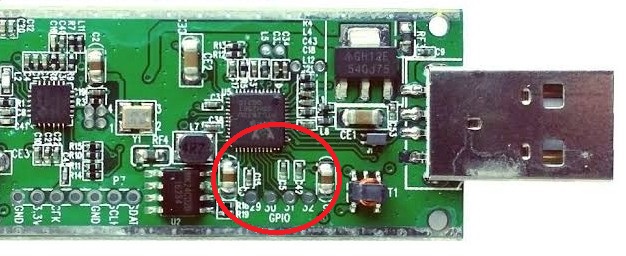
RTL-SDR GPIO header
Use the following table to translate the board numbers to the actual GPIO number:
+---------+-----------+
| SDR PIN |  GPIO NR  |
+---------+-----------+
|   29    |     5     |
|   30    |     4     |
|   31    |     2     |
|   32    |     1     |
+---------+-----------+
RTL-SDR board GPIO and Software GPIO mapping
After installing the required (if your Windows doesn't have it) Windows C++ runtimes, use the rtl_biast.exe file to flip the GPIO signal of interest.
For example, flipping the GPIO Pin 30 to ON:
> rtl_biast -d 0 -b 1 -g 4
The above command translates to:
-
-d 0- RTL-SDR Board #0 (use the proper number if you have more than one dongles) -
-b 1- Enable signal. Conversely, to turn the signal off use-b 0 -
-g 4- GPIO #4, translated from GPIO 30 from aforementioned table
Currently, there are no software provisions to find out the current bias state of each GPIO port. There's a pull request for showing the Bias Tee current state - But nothing involving the individual GPIO ports.