-
Notifications
You must be signed in to change notification settings - Fork 1.4k
Calibrating the VI Sensor

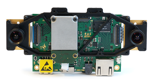
This page will guide you through the calibration of the VI-Sensor (visual-inertial sensor). The intrinsics and extrinsics of the camera system and the transformation of each camera w.r.t. the IMU will be estimated.
More information about the VI-Sensor can be found here.
- prepare the sensor
- setting the focus
- collect calibration data
- in-/extrinsics calibration (static calibration)
- imu-camera calibration (dynamic calibration)
- run the calibration
- in-/extrinsic camera calibration
- imu-camera calibration
- collect results
- ROS sensor driver is running (image/imu data)
- good Aprilgrid target (pdf, yaml)
- Siemens star (or similar camera focus test pattern)
- IMU configuration for ADIS16448 (yaml)
-
make sure the sensor publishes all image and imu streams to ROS
-
minimize the motion blur with a good light source and by reducing the shutter times.
Shutter times can be set using the following commands:
rosrun dynamic_reconfigure dynparam set /visensor_node "{'cam0_agc_enable': 0, 'cam0_aec_enable': 0, 'cam0_coarse_shutter_width': 300}"
rosrun dynamic_reconfigure dynparam set /visensor_node "{'cam1_agc_enable': 0, 'cam1_aec_enable': 0, 'cam1_coarse_shutter_width': 300}"Observe the result on an image window and tweak the shutter until you get a good image:
rosrun image_view image_view image:=/cam0/image_raw &
rosrun image_view image_view image:=/cam1/image_raw &
-
point the cameras on a Siemens star (or similar pattern)
-
start the focus tool
kalibr_camera_focus --topic /cam0/image_raw /cam1/image_raw
-
set the focus of both cameras by:
- reducing the interference visible around the center of the Siemens star
- minimizing the focus measure provided by the tool
Make sure a Teflon band or thread-locking glue prevents unintentional focus changes after this step.
In this step we need to collect two calibration datasets with the following properties:
-
static dataset (in-/extrinsic calibration of the cameras)
- attach the sensor somewhere and move the target
- limit the camera streams to ~4 Hz
- make sure to cover the entire field of view of the camera
- use skewed views and varying distances to the calibration target
view images with:
rosrun image_view image_view image:=/cam0/image_raw &
rosrun image_view image_view image:=/cam1/image_raw &record bag with:
rosbag record /cam0/image_raw /cam1/image_raw -O static.bag
-
dynamic dataset (spatial camera-imu calibration)
- move the sensor (target is fixed)
- cameras should run at 20 Hz and IMU at 200 Hz
- try to excite all rotation and acceleration axes of the IMU
- avoid shocks (e.g. while picking up the sensor)
- good illumination and shutter times are crucial here (to avoid motion blur while exciting the IMU)
view images with:
rosrun image_view image_view image:=/cam0/image_raw &
rosrun image_view image_view image:=/cam1/image_raw &record bag with:
rosbag record /cam0/image_raw /cam1/image_raw /imu0 -O dynamic.bag
-
calibration of camera in/extrinsics
- run calibration
kalibr_calibrate_cameras --models pinhole-equi pinhole-equi --topics /cam0/image_raw /cam1/image_raw --bag static.bag --target aprilgrid_6x6.yaml
- inspect the result plots
- verify calibration on the live image stream
reprojection errors should be in a normal range (0.1-0.2 px for a good calibration)
kalibr_camera_validator --chain chain.yaml --target aprilgrid_6x6.yaml
-
camera-imu calibration
- run calibration
kalibr_calibrate_imu_camera --cam chain.yaml --target aprilgrid_6x6.yaml --imu imu0.yaml --bag dynamic.bag
- inspect the result plots
- make sure the predicted accelerations & angular velocities fit the IMU measurements
- reprojection errors should be in a normal range (0.1-0.2 px for a good calibration)
Both calibrators write reports to the working directory containing the plots shown at the end of the calibration. Further a camchain.yaml has been written by the camera calibrator and is extended by the imu-camera calibrator with imu-camera transformations to the file camchain_cimu.yaml. Please refer to the YAML formats page for the format.
Multiple camera calibration
Camera-IMU calibration
Multi-IMU and IMU intrinsic calibration
Rolling Shutter camera calibration
(only ROS):
Camera focus
Calibration validator
ROS2 support
Supported camera models
Calibration targets
Bag format
YAML formats
IMU Noise Model
Example: Calibrating a VI-Sensor
Example: Calibrating RealSense Cameras