-
Notifications
You must be signed in to change notification settings - Fork 15
Flipper Carbon
George Morgan edited this page Feb 16, 2018
·
4 revisions
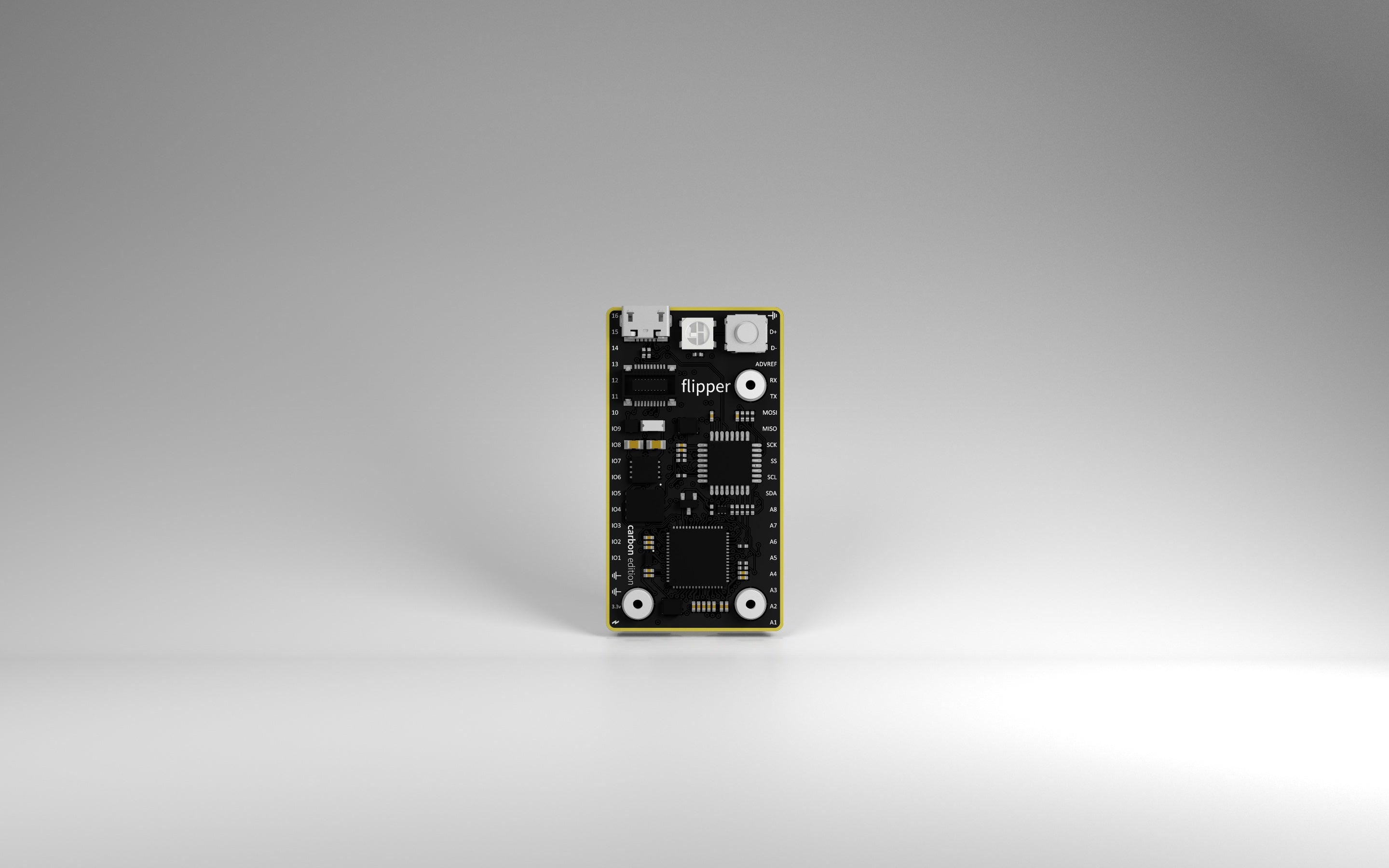
Flipper: Carbon is our flagship embedded development platform. It is an ARM Cortex-M4 powered embedded development platform that is compatible with the Flipper software stack.
| CPU | 120MHz ARM Cortex-M4 |
|---|---|
| Flash | 1MB |
| SRAM | 128KB |
| External Flash | 8MB |
| GPIO | Up to 32 |
| I2C | 2x |
| SPI | 4 slaves |
| USART | 4x |
| DAC | 2x 1024 bit |
| ADC | 8x 1024 bit |
| Timer | 32x |
| PWM | 16x |
| Temperature | 1x |
| RTC | 1x |
All pins are not 5v tolerant. A maximum of 3.3v can be applied to these pins.
| Pin | Mode | Max Voltage (Vmax) | Max Current (Imax) |
|---|---|---|---|
| ⚡︎ | INPUT | 18v in | external supply current |
| ⚡︎ | OUTPUT | 5v out | USB supply current |
| 3.3v | OUTPUT | 3.3v out | 1A out |
| IO* | INPUT | 3.3v in | N/A |
| IO* | OUTPUT | 3.3v out | 20mA out |
| A* | IN | 0-3.6v | N/A |
| A* | OUT | 0-3.6v | 20mA out |
The ⚡︎ can either source or sync current. You can connect an external power supply to this pin to provide power to the board. You can also connect a load to this pin (if the board is powered over USB) to get a 5v signal. No software configuration is needed, simply connect your power source or load to this pin.
| Pin | Name | Notes |
|---|---|---|
| ⚡︎ | Bolt pin | The bolt pin is used to either source or sync voltage from the board. Up to 18v can be applied to this pin to power the board. You can also connect a load to this pin to receive the board's input voltage. |
| 3.3v | 3.3v output | This pin is used to supply 3.3v to external devices. Do not connect this pin to a power supply. |
| ⏚ | GND | Connect all ground references to these pins. |
| IO* | Digital pins | These pins are dedicated GPIO pins and are configured as inputs by default. |
| A* | Analog pins | Connect to the boards DAC and ADC peripherals. A1-A2 are the boards DAC outputs. A1-A8 are the board's ADC inputs. |
| SCL | I2C clock | This pin supplies the clock for external I2C devices. |
| SDA | I2C data | This pin is the data pin for external I2C devices. |
| SS | SPI slave select | This is the board's dedicated SPI slave select pin. The board comes with this pin configured as the SPI slave select pin. |
| SCK | SPI clock | This pin supplies the clock for external SPI devices. |
| MISO | SPI master in slave out | This is the receive (incoming) data line that connects the slave to the master. |
| MOSI | SPI master out slave in | This is the transmit (outgoing) data line that connects the master to the slave. |
| TX | USART transmit | This is the transmit (outgoing) data line that connects the USART bus to an external RS232 serial device. |
| RX | USART receive | This is the receive (incoming) data line that connects the USART bus to an external RS232 serial device. |
| ADVREF | Analog to digital voltage reference | The voltage applied to this pin supplies the ceiling value to the ADC. When this voltage is reached on A1-A8, the 12-bit ADC will read 4095. |
| D- | ~USB data | This is the inverted USB (device mode) data differential pair signal. |
| D+ | USB data | This is the USB (device mode) data differential pair signal. |
| ⏚ | GND | Connect all ground references to these pins. |
Carbon uses two chips together. The purpose that each of these chips serve is described in the Carbon board support package.
