Hardware
The purpose of this wiki page is to discuss and explain the hardware used in the V-Tracker project.
When it comes to building embedded systems, mobile devices and smartphones offer a range of advantages that primarily include: ARM CPU, power supply, battery management, WiFi support, cellular and mobile data support, rich user-interfaces (UI) and much more [7]. Furthermore, “mobile phones have matured as a computing platform and [have] acquired richer functionality, these advancements often have been paired with the introduction of new sensors” [8]. For example, a standard Apple iPhone 4 has eight different sensors: accelerometer, GPS, ambient light, dual microphones, proximity sensor, dual cameras, compass and gyroscope [8].
V-Tracker uses web-technologies to access the mobile device's motion sensors. Using the Apple iPhone 4 as an example, this section will explain the basics behind these sensors.
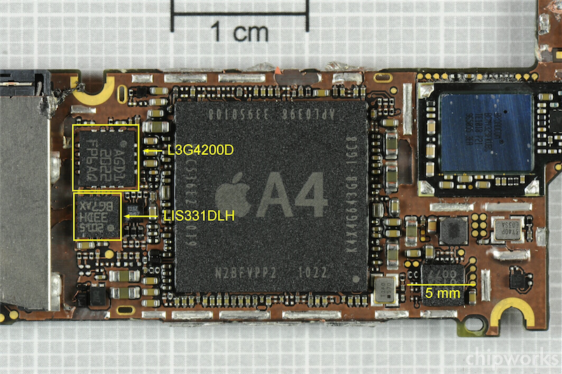
Figure 4. iPhone 4 main board with the STMicroelectronics LIS331DLH accelerometer and the L3G4200D gyroscope side-by-side [9]
A piezoelectric accelerometer can be visualised as a mass suspended using springs. Variations in the physical properties of the springs are detected as the sensor's encompassing body moves. By monitoring the variations in the spring's physical properties, we are able to assert the body's proper-acceleration. In mobile devices, accelerometers are often used to sense the device's overall motion. The accelerometer in the iPhone 4 is a small three degrees-of-freedom (3 dof) STMicroelectronics LIS331DLH three-axis micro electro-mechanical system (MEMS) accelerometer, shown in Figure 4 above. The sensor’s three degrees-of-freedom allow it to provide acceleration data on all three axes as shown in Figure 5. This sensor can be simply described as two cantilever beams that form capacitive plates, with a proof mass attached to the end of one of the beams [9]. Moving the device as a whole moves the cantilever plates closer or further apart. The change in capacitance between the plates creates a signal that is measured using an on board Application Specific Integrated Circuit (ASIC) [9]. The ASIC is also used to maintain the spacing between the plates (i.e. the capacitance) by using capacitive feedback to maintain a constant DC bias across the plates [9].
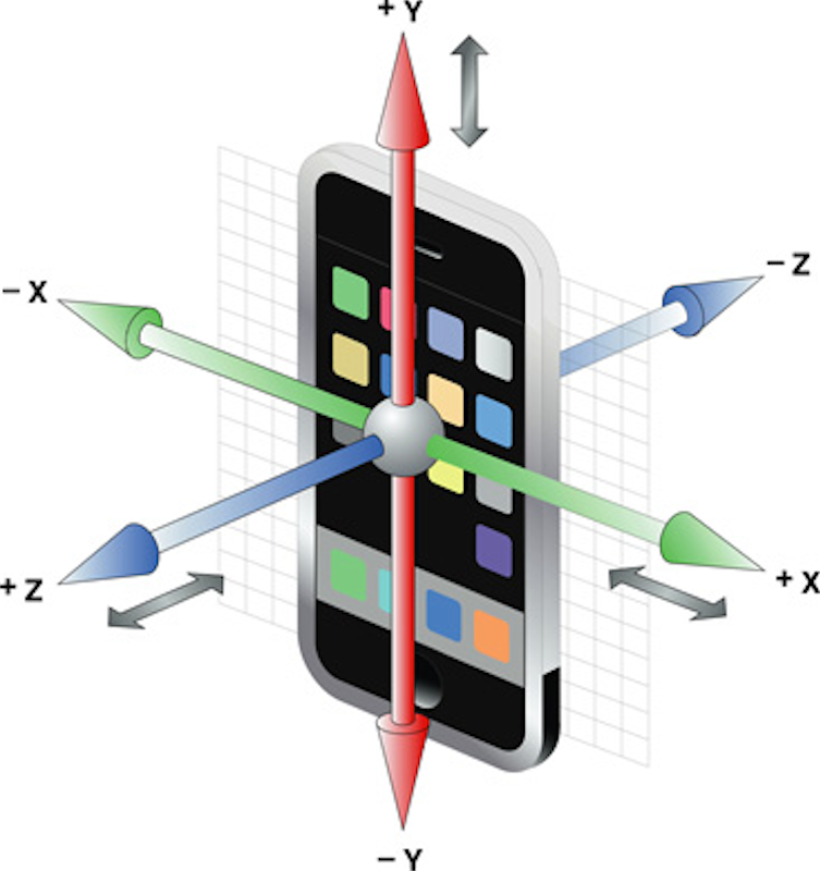
Figure 5. The 3 dof accelerometer on the iPhone 4 provides acceleration readings on the x, y and z axes [10]
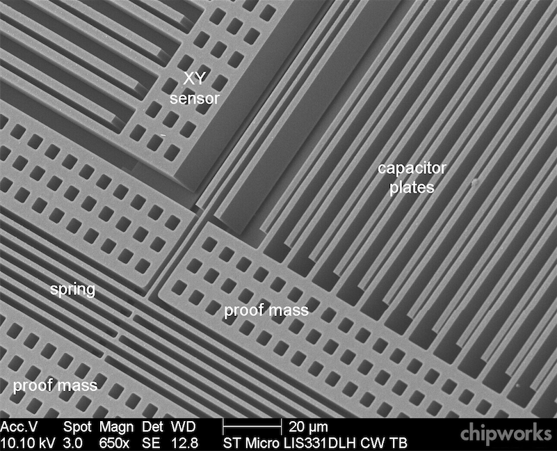
Figure 6. LIS331DLH XY accelerometer sensor detail [9]
Selecting an interval that minimises the number of calls to the sensor will improve the device's battery life. It is therefore recommended that the update interval be appropriately set for the intended use case. Table 1 below is extracted directly from the Event Handling Guide for iOS and describes some of the more common update intervals chosen for acceleration events. Naturally, these intervals can be interpolated or extrapolated for unique uses. These intervals can also be specified for applications deployed on different mobile operating systems, provided of course that the device’s sensor can respond at the frequencies specified.
Acceleration data is typically returned in the form of a three-dimensional vector with x-axis, y-axis and z-axis components. The acceleration data returned in iOS includes a gravity component, which can be isolated or filtered to suit specific applications.
| Event frequency (Hz) | Usage |
|---|---|
| 10–20 | Suitable for use in determining the vector representing the current orientation of the device. |
| 30–60 | Suitable for games and other applications that use the accelerometers for real-time user input. |
| 70–100 | Suitable for applications that need to detect high-frequency motion. For example, you might use this interval to detect the user hitting the device or shaking it very quickly. |
If you are using the accelerometer sensor to detect a device's orientation for example, it is suitable to filter out shakes and spikes from the acceleration data. In other words, in order to better detect a device's orientation, we only want the gravity component of each axis on the sensor. To do this we need to isolate the gravity component from the rest of the accelerometer data. The iOS Dev Center recommends a basic low-pass filter to reduce the effects of sudden jolts, shakes, or movements [10]. The filter can be implemented as follows:
// Use a basic low-pass filter to keep only the gravity component of each axis.
accelX = (acceleration.x * kFilteringFactor) + (accelX * (1.0 - kFilteringFactor));
accelY = (acceleration.y * kFilteringFactor) + (accelY * (1.0 - kFilteringFactor));
accelZ = (acceleration.z * kFilteringFactor) + (accelZ * (1.0 - kFilteringFactor));

// Use accelX, accelY, accelZ to do stuff…
Code snippet 1: Isolating the gravity component (low-pass filtering) [10]
The kFilteringFactor can be used to specify the sensitivity of the filter. A low-value filtering factor of 0.15 (or 15%) was found to be suitable for most applications in V-Tracker.
If you are using the accelerometer to detect sudden movements such as shakes, it is recommended that a high-pass filter be used to reduce the effects of gravity [10]. The filter can be implemented using a technique similar to that in low-pass filtering.
// Subtract the low-pass value from the current value to get a simplified high-pass filter
accelX = acceleration.x - ( (acceleration.x * kFilteringFactor) + (accelX * (1.0 - kFilteringFactor)) );
accelY = acceleration.y - ( (acceleration.y * kFilteringFactor) + (accelY * (1.0 - kFilteringFactor)) );
accelZ = acceleration.z - ( (acceleration.z * kFilteringFactor) + (accelZ * (1.0 - kFilteringFactor)) );
Code snippet 2: Isolating instantaneous motion (high-pass filtering) [10]
Unlike the accelerometer and compass, which rely on external forces, a gyroscope measures its own rotation. To do this, gyroscopes rely on the Coriolis effect or the perceived deflection of a moving object when observed from a rotating frame of reference. The iPhone 4 is equipped with a MEMS three degrees-of-freedom STMicroelectronics L3G4200D gyroscope that uses the Coriolis effect [11].
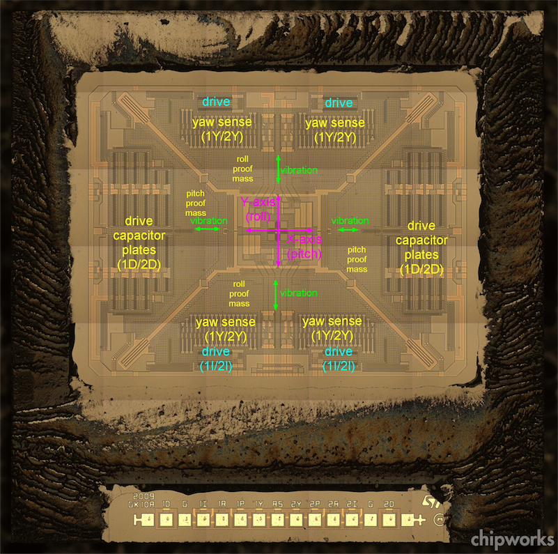
Figure 7. L3G4200D GK10A three-axis gyroscope die [11]
The figure above shows the die for the GK10A three-axis gyroscope. The drive capacitor plates seen on the figure are used to vibrate four proof mass elements. The vibration of the proof mass elements is managed via a spring that can be better seen in the figure below. As the device is rotated, differential out-of-plane deflection can be sensed by poly-silicon capacitor plates located beneath the proof mass elements [11].
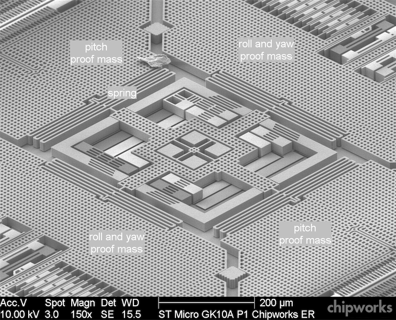
Figure 8. L3G4200D detail [11]
Gyroscopes in mobile devices only sense angular velocity or "the rate at which a device rotates around each of its spatial axes" [10]. In order to assert the device orientation using the gyroscope, it is necessary to rely on the accelerometer and compass (or magnetometer) sensors and utilise a series of filtering techniques to combine data from all three sensors. The accelerometer and compass (or magnetometer) are also used to regularly compensate for gyroscope drift. The three degrees-of-freedom gyroscope on the iPhone 4 provides angular velocity on all three axes. Like the accelerometer, the gyroscope uses the right-hand coordinate system shown in Figure 9 below. As a result, the positive angle of rotation can be determined using the right hand rule, which is visualised in Figure 10.
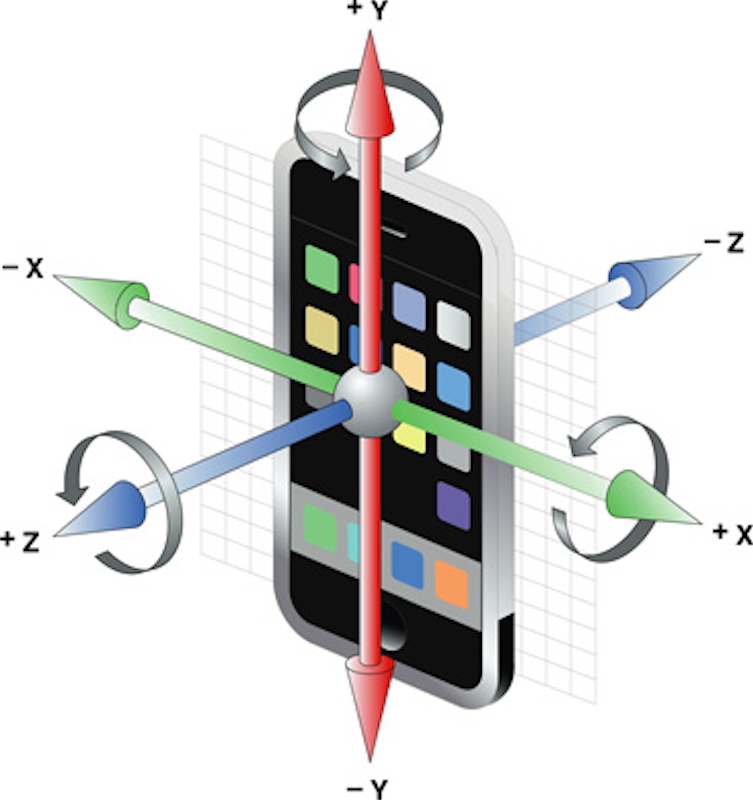
Figure 9. The 3 dof gyroscope on the iPhone 4 provides roll, pitch and yaw angular velocities [10]
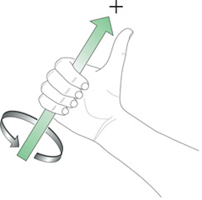
Figure 10. The direction of an axis' positive angular change can be found using the Right Hand Rule [10]
V-Tracker also uses web-technologies to access the mobile device's localisation sensors. Again using iOS and the Apple iPhone 4 as a guide, this section will explain the basics behind these sensors.
In mobile devices, the compass (or magnetometer) is used to assert Magnetic North. The iPhone 4 has an AKM AK8975/3 magnetic sensor that uses the Hall effect to sense its orientation relative to the earth's magnetic field [12]. A current is passed between the two contacts on the Hall sensors and the perpendicular effects of the Earth’s magnetic field are captured and processed [12]. As a result of the technique used for the magnetometer, it is common for the sensor to suffer from environmental interference and therefore requires regular calibration.
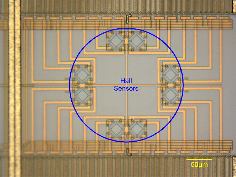
Figure 11. AK8973 Hall sensor layout [12]
The compass in the iPhone 4 is a three-axis sensor that can provide heading data regardless of the device's orientation in space. When combined with the accelerometer and gyroscope, these three sensors provide sensing information on nine degrees-of-freedom. The iPhone’s magnetometer can be seen on the circuit board in the Figure below.
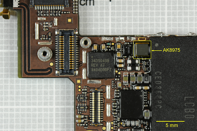
Figure 12. iPhone 4 main board with the AKM AK8975 electronic compass [12]
Global Positioning System (GPS) receivers have become a common feature of modern mobile devices and form an integral part of V-Tracker. GPS and location services provide geographical context and allow developers to build location aware applications such as maps-supported navigation [13]. The Global Positioning System itself was setup by the U.S. Department of Defence in the 1970s and today consists of a constellation of 24 active satellites and 5 reserves [14]. Although originally intended for military use, the GPS is now available for civilian use with no subscription or setup fees [14]. Each GPS satellite travels on a precise orbit and its Ephemeris data (data that indicates where a satellite is throughout the day) is programmed into GPS receivers [14]. In order to find a user’s location, a GPS receiver transmits a signal to its nearest satellites and measures the time taken for the transmitted signal to be returned from each satellite. The time differences can then be used to calculate the distance to each of the satellites pinged [14]. Fundamentally, GPS receivers are able to combine Ephemeris data and signal transmission time measurements with simple trilateration techniques to reliably assert a user’s location to an accuracy radius of approximately 10m. A minimum of three satellites is required to determine a user’s location with reasonable accuracy.
Several factors that contribute to errors in GPS signals do so by degrading the signal and affecting its accuracy [14]. Some of these factors include: ionosphere and troposphere delays, signal multipath, receiver clock errors, orbital errors, number of satellites visible, satellite geometry/shading and intentional degradation of the satellite signal [14].
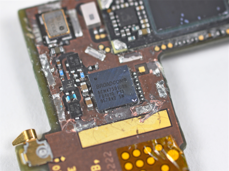
Figure 13. The Broadcom BCM4750IUB8 single-chip GPS receiver [15]
The iPhone 4 has a Broadcom BCM4750IUB8 single-chip GPS receiver [15], which can be seen in the figure above. The BCM4750 is a single-chip, single-die, low power Assisted-GPS (AGPS) solution that is optimised for mobile devices [16]. The receiver supports update rates of up to 2Hz [16]. Assisted-GPS chips are able to utilise alternative radios such as WiFi and GSM to improve the time-to-first-fix on GPS based positioning systems.
On the iPhone 4, Apple has integrated the UMTS, GSM, GPS, Wi-Fi and Bluetooth antennas into the stainless-steel inner frame [15]. This is shown the figure 14.
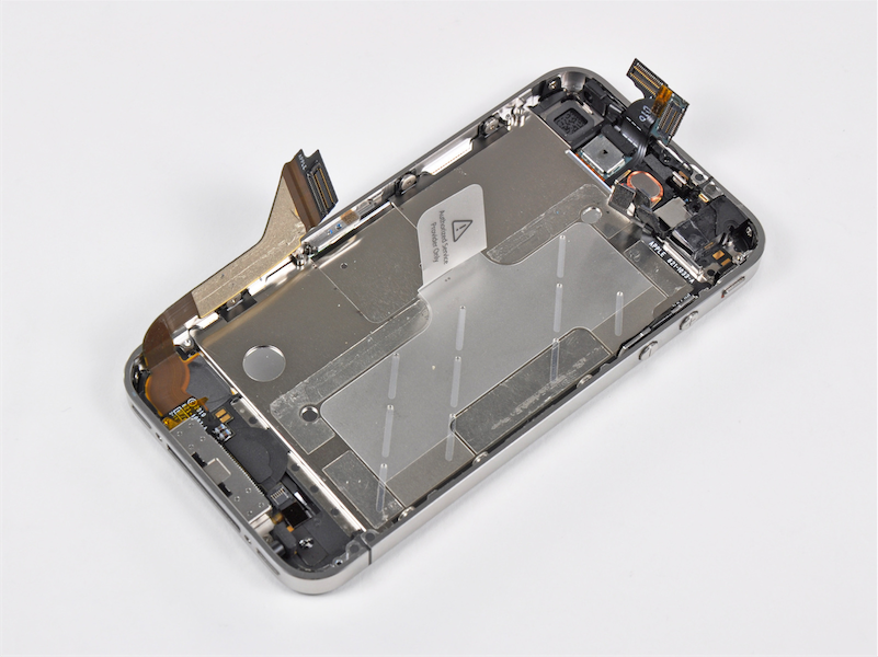
Figure 14. The iPhone 4's integrated UMTS, GSM, GPS, Wi-Fi and Bluetooth antennas on the stainless steel inner frame [15]