-
Notifications
You must be signed in to change notification settings - Fork 8
Home
The STM32 family of chips is quite vast with lots of different configurations. ST microelectronics provides a tool names STM32CubeMX which allows to select one of the STM32 processors and gives the user the possibility to configure its clocks and peripheral interfaces. STM32CubeMX then generates C code template in which the peripherals are initialized. In addition include files and library code to access the peripherals and Makefile are included into a package which can be read into Eclipse as an Eclipse project.
Eclipse must have the stm32 workbench installed to make this work. The programmer adds his own code into main.c of the package generated by STM32CubeMX and builds the project with Eclipse. Using the Open On Chip Debugger openocd the compiled code can be flashed into the target flash. This is done using an STLink V2 debugging probe and its associated software from within Eclipse. The Eclipse debugger, which is associated with arm-none-eabi-gdb can then we used to debug the code setting breakpoints, single step the program or looking at its variables.
In order to make all this work we need the following hardware:
- A STM32 processor.
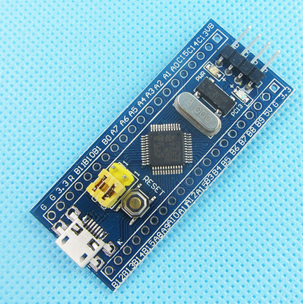
- I use the stm32f103c8t8 minimum development system (also nick-named blue pill) which you can buy at Aliexpress for less than 2 US$
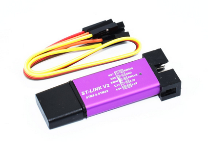
- The STLink V2 debugging probe again for ~ 2US$. This probe actually contains an stmf103cbt8, which is the same chip as our target processor but uses 128 kBytes of flash as compared to the stm32f103c8t8 which has 64kBytes. (This is what is announced when reading the chip but in fact there are usually also 128 kBytes available, but not guarantied to work)
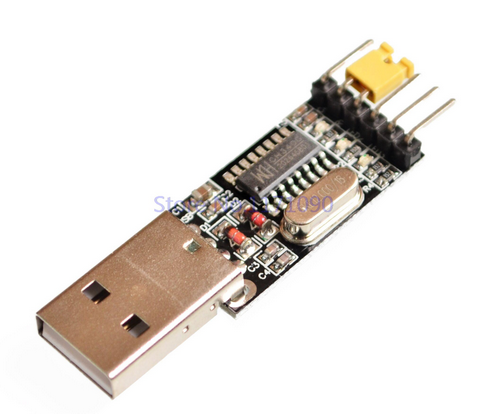
- A USB to serial adapter. The stm32f103c8t8 has a bootloader working with a serial line included in ROM. When something goes wrong we can always erase the flash and reset the device using a programming tool based on a USB to serial adapter.
 |
 |
 |
|---|---|---|
| STM32F103C8T6 | ST-Link V2 probe | USB to Serial adapter |
From the software point of view we need:
- STM32CubeMX from ST microelectronics, the processor configurator and code generator
- Eclipse and the STM32 workbench plugin
- The STLink software tools
- The stm32loader.py Python script
First we install STM32CubeMX which you find at https://www.st.com/en/development-tools/stm32cubemx.html. When downloading the software you will get a zip file named en.stm32cubemx.zip. unzip it and use SetupSTM32CubeMX-4.26.0.linux to install the package.
Next we need the eclipse plugin. Start eclipse and select Help -> Install New Software and add the new repository at http://ac6-tools.com/Eclipse-updates/org.openstm32.system-workbench.update-site-v2
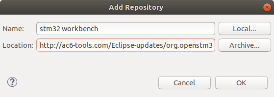
Now install all plugins from this site.
The tools for the STLink V2 debugger probe can be found at https://github.com/texane/stlink. Download and build the tools:
git clone https://github.com/texane/stlink.git
make
You will find the binaires + shared library under build/Release. Some further tools are under build/Release/src.
Installing openocd is simple (if it is not already installed) as it is part of the Ubuntu repository. Therefore sudo apt install openocd will do the trick.
Make sure that all these binaries are visible in the execution path.
Finally we download the Python script which allows us to flash the stm32f103c8t3 through the USB to serial converter. You find it at https://github.com/jsnyder/stm32loader.
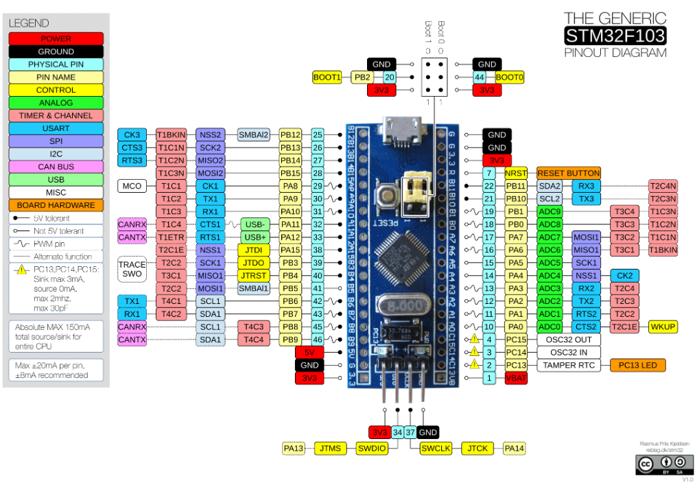
On the stm32f103c8t6 the user LED is connected to pin 13 on GPIO port C, therefore PC13.
Here is the pinout of the blue pill board:
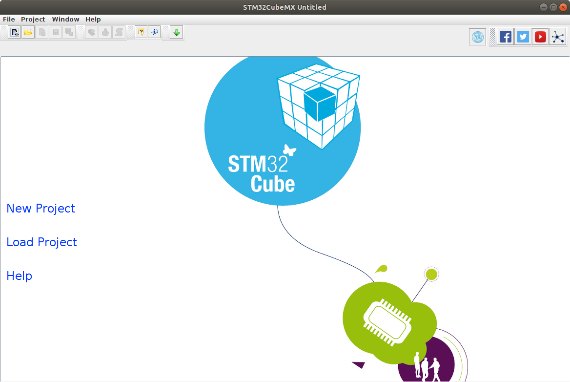
Start STM32CubeMX, create a new project and select the stm32f103c8 chip:
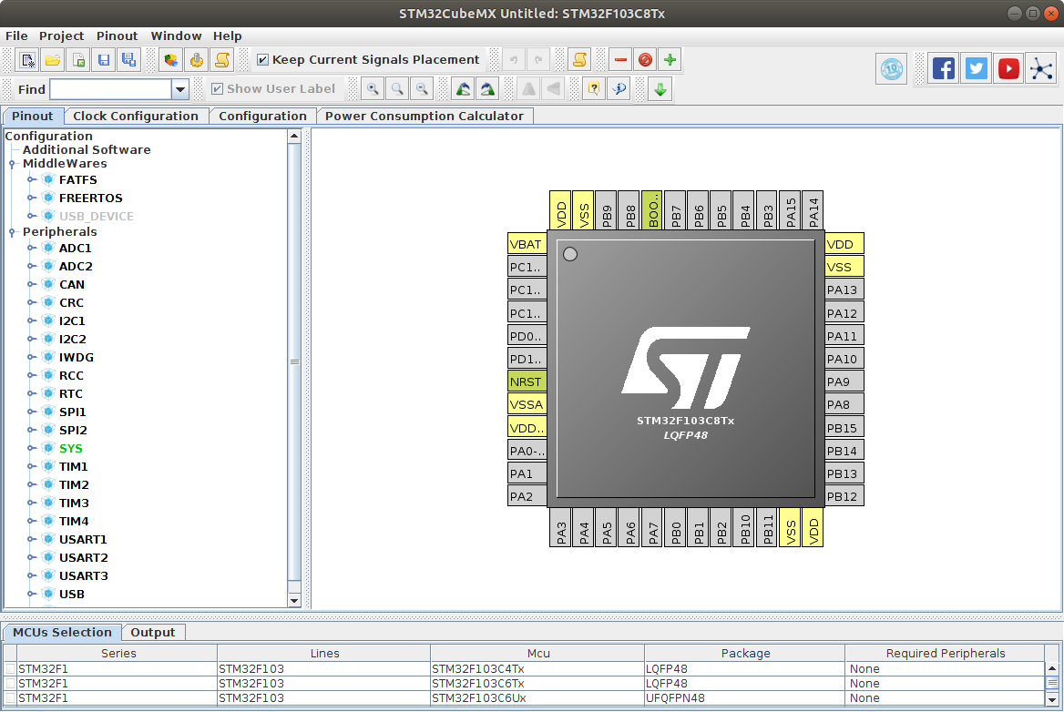
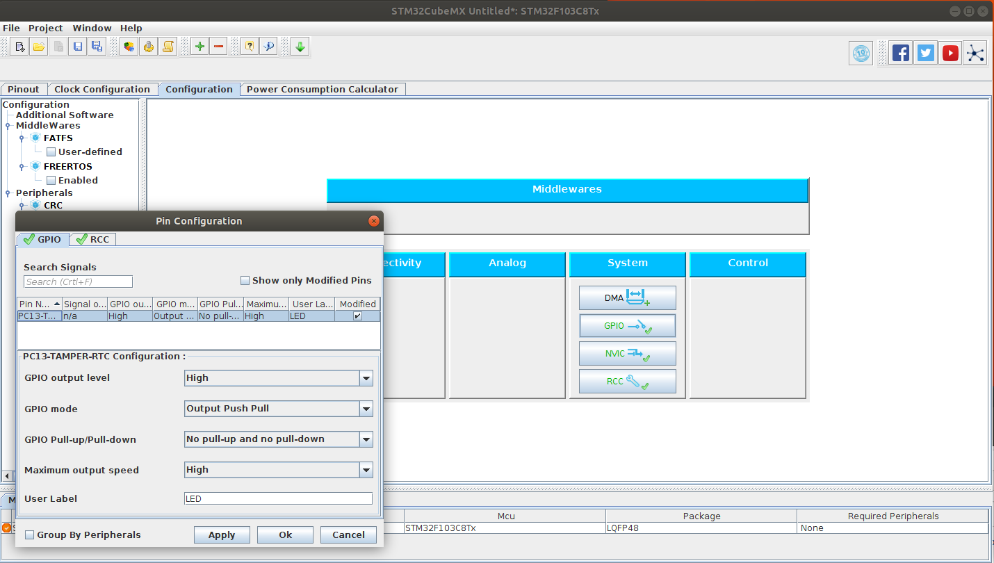
When starting the project we will get a diagram of the chip pinout and we can select the pin functions. First expand the SYS folder and select Serial Wire as debug function. Then expand RCC and enable the high speed clock with Crystal/Ceramic Resonator. Finally click on the pin below VBAT (PC13-TAMPER_RTC) and select GPIO_Output. The pins selected this way will turn green on the pin diagram.
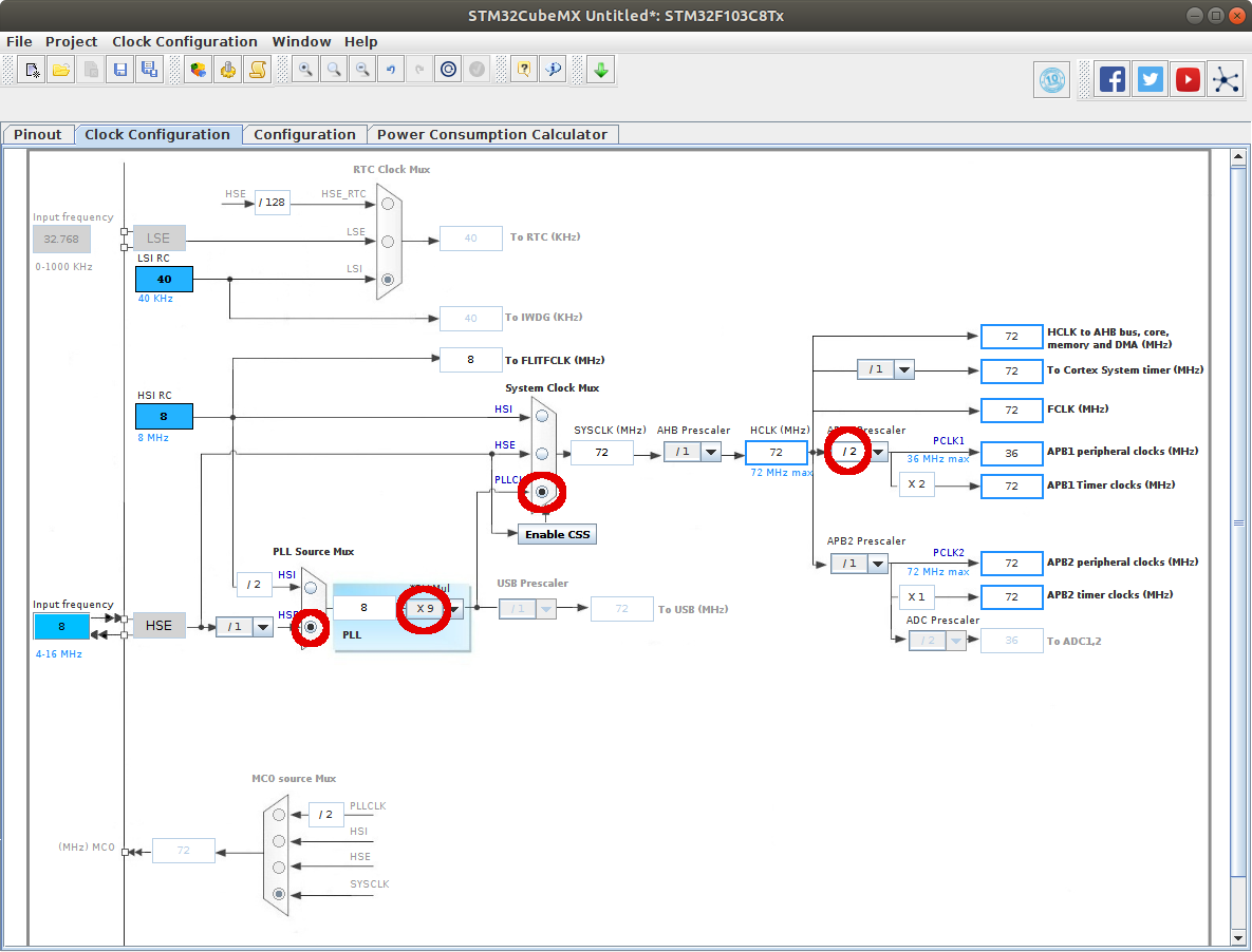
I selected the high speed clock from the 8MHZ input, increase thee frequency by 9 in the PLL and divided it down again by 2 to end up with 36 MHz on the ABP1 peripheral clocks. Change the parameters as shown.
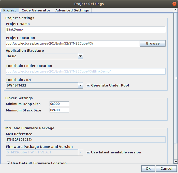
Finally we are ready to generate the project code. Select Project -> Settings, give a project name and select the SW4STM32 IDE.
Now start eclipse. Once eclipse is up, select Import Project on the STM32CubeMX window saying that code generation was successful.

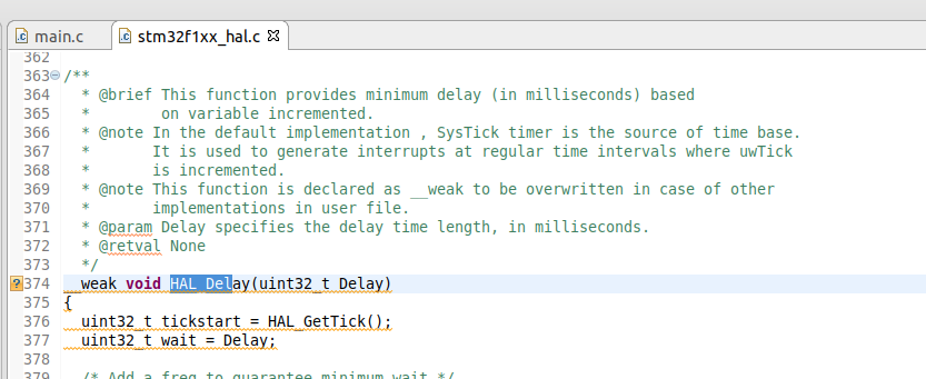
In the project's endless loop we will have to add code to switch the GPIO Pin 13 on and off as well as calls to a delay routine waiting for some 500-1000 ms between each switch. These functions are available in the HAL (Hardware Access Layer) library whose source code is added to the project by STM32CodeMX. HAL_Delay(uint32_t Delay) is defined in stm32f1xx_hal.c which you find in the Drivers directory. The parameter Delay is a value given in ms.
The routine to set and reset the GPIO pin is provided by stm32f1xx_hal_gpio.c:

The code we have to add therefore looks like this:
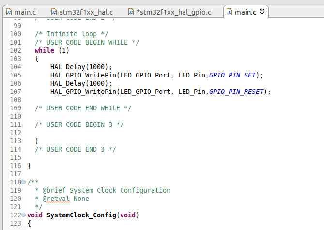
Now we are ready to build the project. Select it, right click on it and select and select
- Clean Project followed by
- Build Project
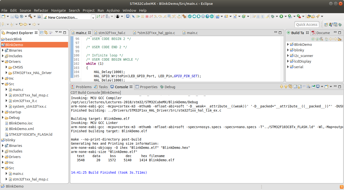
Make sure there are no compilation errors!
Next we must flash the newly built project. Connect the STLink probe to the BluePill board as indicated on both devices.
- SWCLK
- SWDIO
- GND
- 3.3V must be connected. Plug the STLink probe into the PC.
lsusb should show you the ST-LINK/V2 device.

In order to flash the code we start the debugger clicking the down arrow on the bug symbol and select Debug as Ac6STM32 C/C++ application.
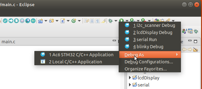
Unfortunately this did not work in my case as eclipse did not find arm-none-eabi-gdb, the debugger. I find that in my installation ~/.p2/pool/plugins/fr.ac6.mcu.externaltools.arm-none.linux64_1.16.0.201807130628/tools/compiler is an empty directory. I replace it with a link to st-gnu-arm-gcc-7-2017-q4-major_gdb-5_4-2016q3
This brings me a little further:
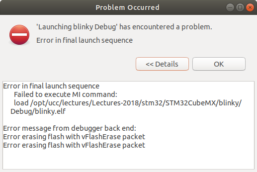
I cannot access the target with st-flash any more. In this case all I managed to do is erasing the flash using the serial line.
Connect Tx of the USB to serial converter to A9 and Rx to A10 of the BluePill.Connect 3.3V and GND. Set the boot0 jumper to 3.3V. Insert the USB to serial converter into the PC and erase the stm32 flash with stm32loader.py -e -p /dev/ttyUSB0.

After this procedure everything worked fine again if I did not forget to set the boot0 jumper back to GND.
Being able to print debugging information to a console can be a great debugging help and it allows to visualize results like readout values from sensors. In order to do this we must first enable the USART, which can easily be done with STM32CubeMX:
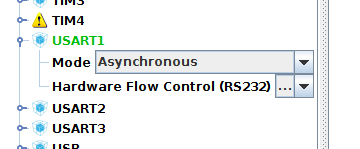
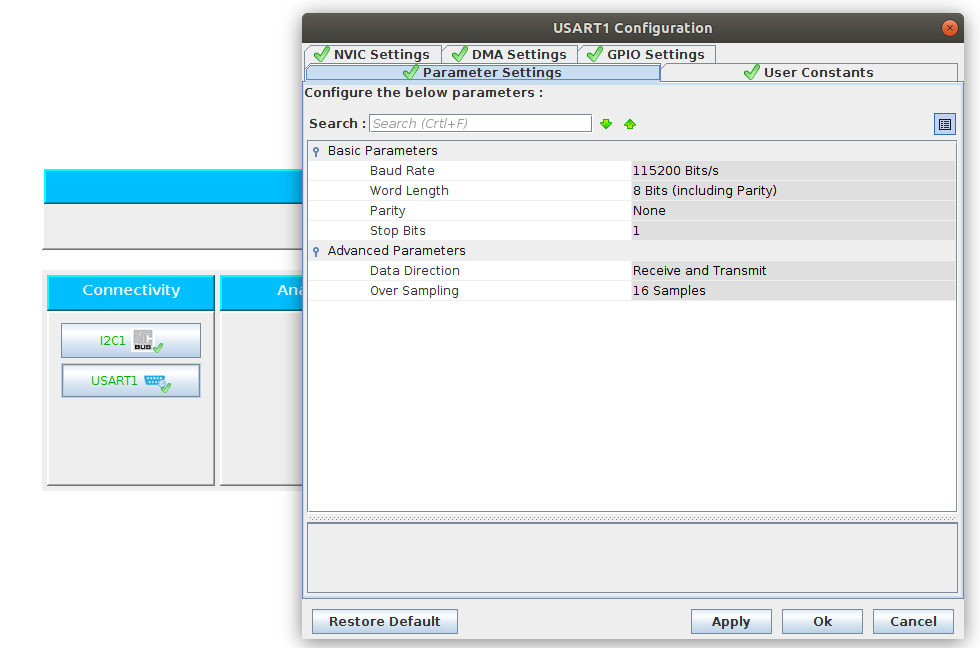
When we enable the USART to be an asynchronous port we immediately the to which the Rx and Tx signals of the port art connected. Hook PA10 up to the Rx line of an USB to serial converter and PA9 to its Tx and insert the USB to serial adapter into the PC's USB slot. Clicking on the Configuration tab in STM32CubeMX and then on USART1 brings up a window showing the default configuration (which fits us well).
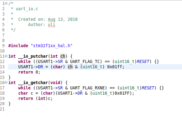
After code generation we can get access to the USART. The HAL library has routines giving access to the port like HAL_UART_Transmit and HAL_UART_Receive but it is also possible to the standard C printf call. In order to enable this copy syscalls.c from your STM32CubeMX distribution (STM32CubeMX _Installation_Dir/db/plugins/projectmanager/src/syscalls.c) to the Src directory of your project. Having a look at the beginning of the code shows us that all we have to do is overriding the __io_putchar and __io_getchar. I add a C file named uart_io.c with the following contents to the Src directory:
Now you can try a "Hello World" program printing the text with printf.
Any formatted printf work ... except printing floating point numbers. Unfortunately floating point printing is disabled in the compiler by default. This however can be corrected:
Right click on the project name in eclipse and select properties. Click on C/C++ build -> Settings (this may take a while to come up). Select MGU GCC Linker -> Miscellaneous and add -u _printf_float to the Linker flags. That's all! Now a print statement like this (from the BPM280 temperature and barometric pressure sensor library description)

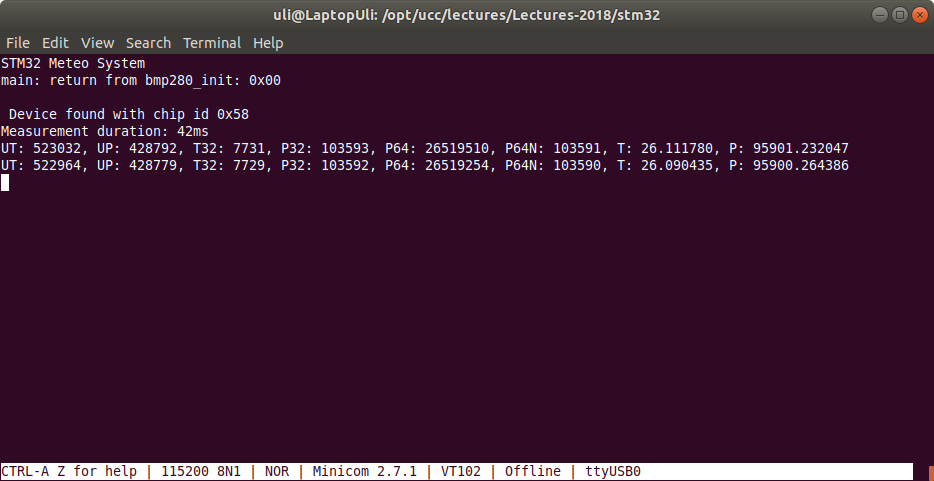
has the expected result in minicom connected to the USART:
