Lap timer building
IMPORTANT NOTE: the software assumes that LANE 1 is the left one. Make sure of this when you attach the sensors/LEDs.
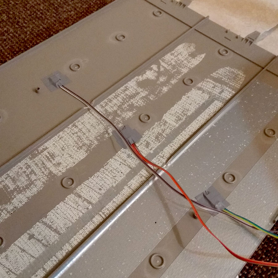
- Drill 3 holes in the middle of the 3 lanes of a mini4wd track piece. Put the sensors under the holes and fix them with tape.
- Build some sort of bridge-like structure to hold the electronics.
- Put the structure over the 3 holes on the track with the sensors. The mini4wd car passing over the phototransistors will trigger a lap.
- Attach the lasers underside the bridge, so that they are exactly pointed at the phototransistors.
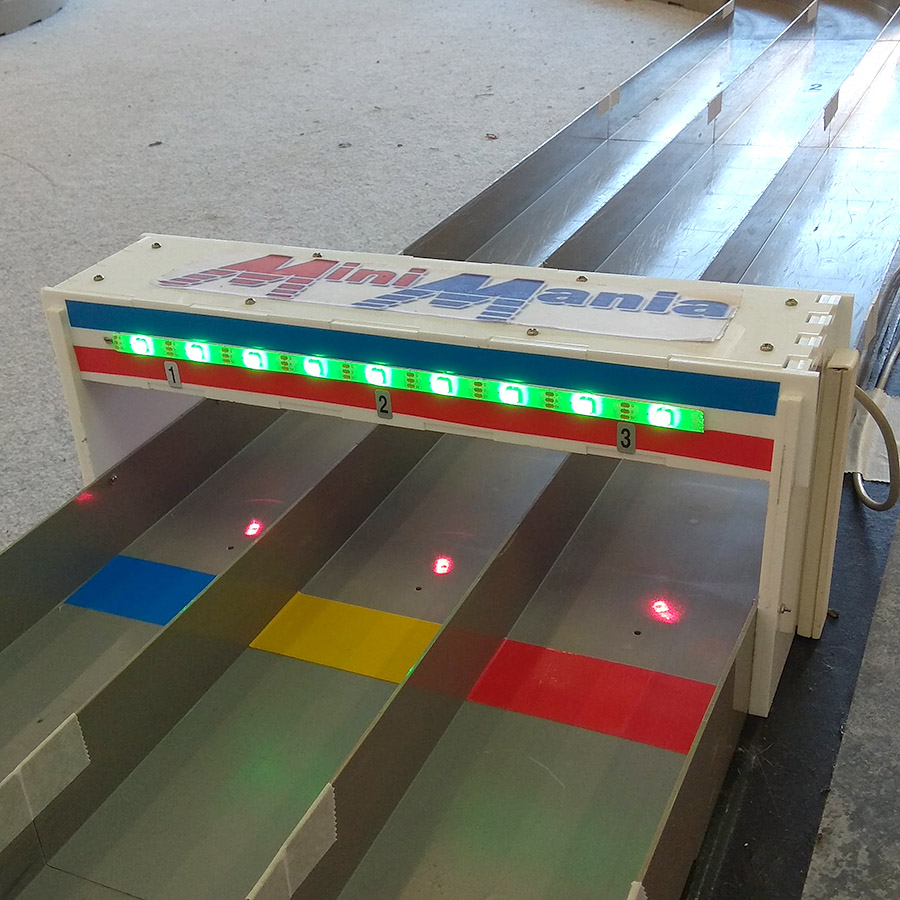
- If using 3 green LEDs, put them on the front of the lap timer, one over each lane.
- If using a LED strip, attach it on the front of the lap timer, ensuring the arrows on the strip are pointing to the right (going from lane 1 to lane 3).
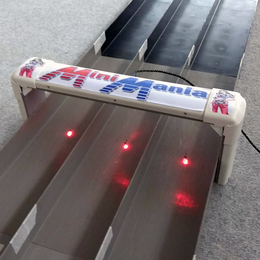
Example lap timer made using cable ducts:
More elaborate lap timer with LED strip and polycarbonate body: