Assembly Guide
Contents:
Important
Please ensure you read the Safety section.
It is highly recommended to thoroughly read this guide and consult the CAD Assemblies before and during the build process.
The models have been designed to reflect a real build as close as possible and will serve as your main reference guide.
The CAD Viewer Primer contains a series of videos on how to use the Online CAD Viewer for component identification, assembly isolation, etc.
Disclaimer
This is a DIY (Do-It-Yourself) experimental project. This information is provided "as is" without any guarantees or warranty, and is not certified for any commercial or critical applications. Use it at your own risk. The creator assumes no liability for damages or injuries resulting from its use, including but not limited to fire, electric shock, personal injury or property damage. By using this you agree to the terms of this disclaimer.
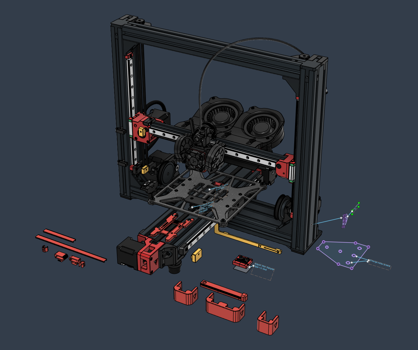
Printer - Online CAD Viewer
Toolhead - Online CAD Viewer
Ebox - Online CAD Viewer
Aux Fan - Online CAD Viewer
Breakout Box - Online CAD Viewer
Important
The CAD Viewer Primer contains a series of videos on how to use the Online CAD Viewer for component identification, assembly isolation, etc.
Additional images from the LH Stinger prototype build are available in the Build Log section.
Please feel free to join the LH Stinger Discord server to ask for advice, or to study other LH Stinger builds.
- This is an advanced build, so please take your time to prepare beforehand, and to get familiar with this guide and the CAD models. The process of building this printer requires a different mindset than other popular models, and you will be required to have the Online CAD Viewer opened to reference the exact hardware components needed during the assembly process.
- It is highly recommended to view the tutorials from the Cad Viewer Primer page to learn how to use this resource most efficiently.
- Please follow the step by step instructions where available. The order of assembly is crucial for some sub-assemblies, and failing to follow it will result in a lot of frustration and backtracking.
-
The processes below should be done beforehand to have the components ready at assembly time:
- Printed Parts
- Cleaning and lubing the Linear Rails
- CF-Carriage-Assembly
- Bed Heater
Must read information regarding kits will be tracked and updated on this wiki.
FYSETC: https://github.com/lhndo/LH-Stinger/wiki/FYSETC-Kit
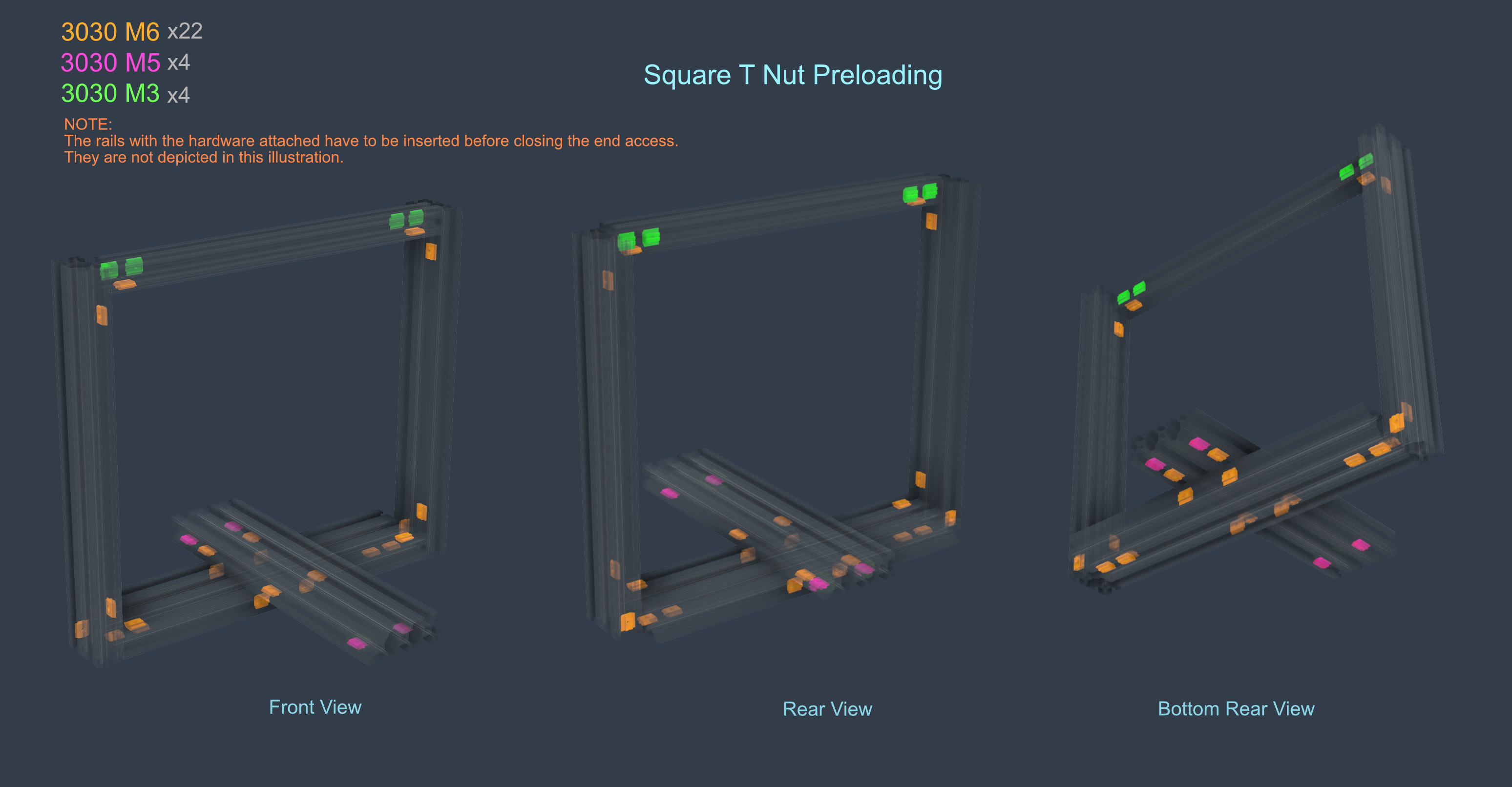
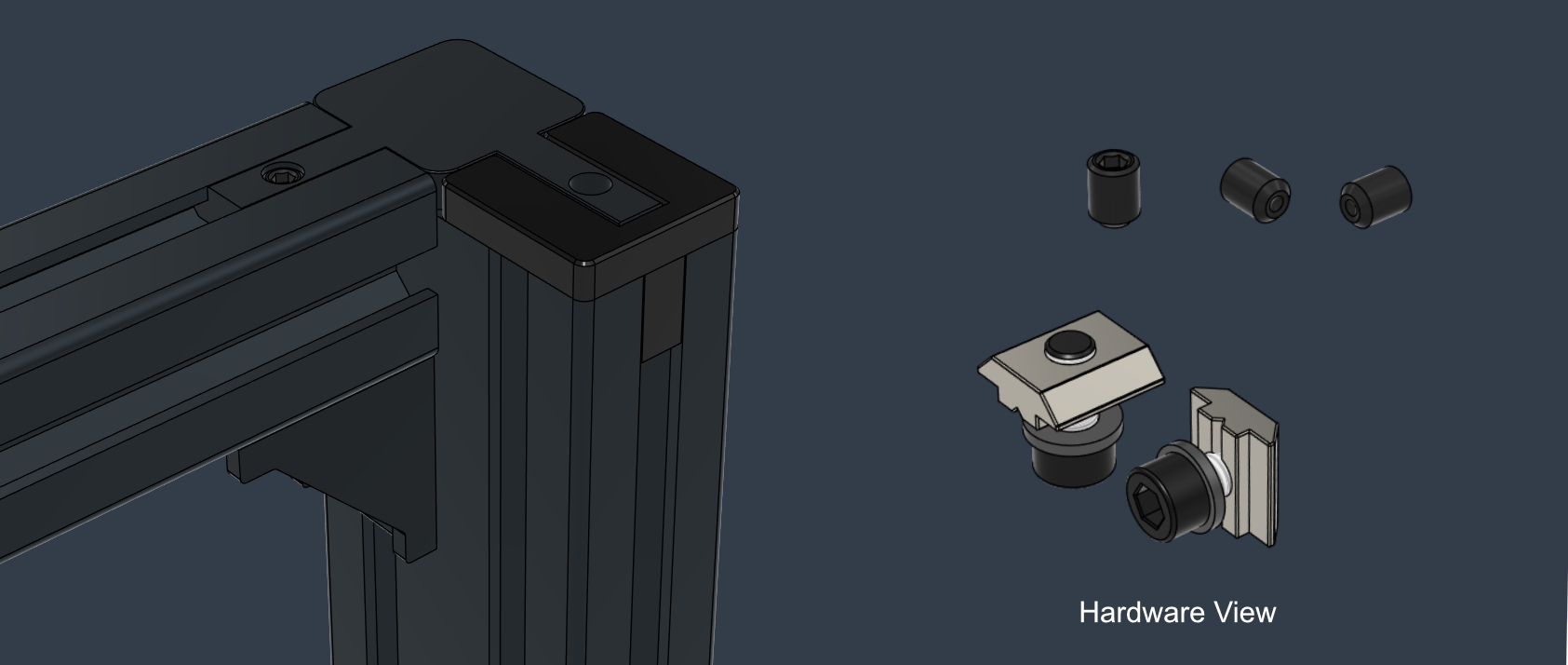
- Please come back to this section whenever you permanently close both ends of an extrusion member
- You are not required to preload all the square nuts illustrated below before starting the assembly process
- It is often easier to attach the brackets and hardware to one of the extrusion member and then sliding it into the corresponding part (as illustrated in the Frame Assembly section below)
- Remember to insert the Z linear rails as instructed before closing the frame
The Other Parts.3mf file contains an additional set of parts designed to aid you during the assembly process.
It is recommended to print these parts and refer to the CAD Printer assembly for instructions on their usage.
They are also provided as individual STLs if needed.
Tip
Clips for holding T-nuts into position (from each side) can be found among these parts, and can be positioned by inserting a hex key into the circular hole.

Frame Extrusions
| Type | Item | Quantity |
|---|---|---|
| X Extrusion | 2020 - 323mm | 1 |
| Y Extrusion | 3090 - 345mm | 1 |
| Z Extrusion | 3060 - 400mm | 2 |
| Top Extrusion | 3030 - 400mm | 1 |
| Bottom Extrusion | 3090 - 400mm | 1 |
-
Due to the modular nature of the design, you are free to build the main assemblies in any order you like.
-
My personal preference is to approach the build in the following sequence: EBox > Toolhead > Main Frame > X Axis > Y Axis.
📘 It is recommended to assemble the Y axis independent from the rest of the frame and to mount it onto the printer in the end.

- If your extrusions did not come pre-tapped, then the following areas will have to be tapped to accommodate M8 screws.
- The highlighted brackets are not made for M8 screws, so the holes marked in blue will have to be enlarged with a drill.
Note
If you bought a kit with extrusions and brackets pre-tapped and drilled, make sure to check their orientation before assembly. The tapping might have been done selectively and requires attention when matching them. Same with bracket selection.

The printer was design to be assembled using Die-Cast metal brackets. This will add extra rigidity to the assembly, and ensure that you don't have to rely on the precision of extrusion cuts. Even so, the quality of the brackets is important, and checking for their squareness before assembly is recommended. Don't be afraid to shim parts where needed to achieve a square fit!
- Since the main frame is composed by only four extrusions, it is worth spending some extra time during assembly to ensure it is as square as possible.
- The nature of the high preload rails require precise alignment and care. You will be able to notice small deviations during the carriage movements, and provide feedback if something is not right, or if it binds.
- This is a by-product of the design decisions, and will ensure the printer is assembled as well as possible.
The most valuable tool during this process is an Machinist Square.
You can find a link to the one I use in the bottom Tools section of the BOM
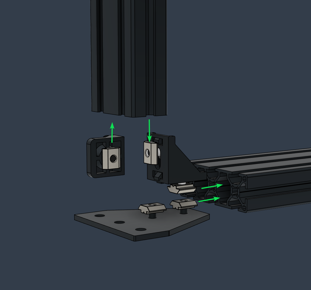
Side Bottom Bracket Assembly (x2)
| Type | Item | Quantity |
|---|---|---|
| Bracket | Cast 90 Degree Corner 3030 - 6 Slot | 1 |
| Bracket | Cast 90 Degree Corner 3030 - No tabs | 1 |
| Plate | Joining Plate 3030 | 1 |
| Foot | Hard Foam Pad | 1 |
| T-Nut - Square | 3030 - M6 | 5 |
| Washer | M6 12x1.6mm | 2 |
| Screw Button Head | M6 10mm | 2 |
| Screw Button Head | M8 16mm | 3 |
| Screw Countersunk | M6 14mm | 1 |
| Screw Socket Head | M6 12mm | 2 |
Top Bracket Assembly (x2)
| Type | Item | Quantity |
|---|---|---|
| Bracket | Cast 90 Degree Corner 3030 - 6 Slot | 1 |
| Bracket | Hidden Three Way Corner 3030 | 1 |
| Screw Socket Head | M6 12mm | 2 |
| T-Nut Square | 3030 - M6 | 2 |
| Washer | M6 12x1.6mm | 2 |
| Grub Screw | M6 8mm | 3 |
Preloaded T-Nuts are included in the tables above
Note
It is recommended to use Threadlocker for the screws part of the Frame assembly.
Loctite cannot touch printed parts, or they will degrade. Use it only for pulleys and large metal to metal assemblies.
Double check the squareness between each member during and after the assembly of each component.
Tightening the screws can pull things out of alignment.
- Start with the main bottom 3090 - 400mm extrusion and attach the left 3060 - 400mm Z extrusion.
❗ Check if the tapped M8 holes at the ends of the bottom extrusion match the required orientation!
Tip
If the frame members are not closed on both sides, it is then easier to pre-load the sub-assemblies that use T-nuts by loosely attaching the screws and sliding them in.
-
After these are square and fully tightened, preload the required Square T-Nuts and attach the second Z extrusion.
-
Proceed with the rest of the preloaded Square T-Nuts
-
Insert the MGN 12H 250mm Z linear rails before attaching the top extrusion and closing the frame ❗
-
Insert the top 3030 400mm extrusion with its set of preloaded Square T-Nuts
- The top needs to be tightened in such a way that it keeps the previous squareness in place, and doesn't add any forces that would shift things out of alignment
- Do not use the top extrusion to bring things into alignment. Due to the stiffness of the brackets it can bend the aluminum frame.
X Rail:
| Type | Item | Quantity |
|---|---|---|
| Linear Rail | MGN 12H 300mm | 1 |
| T-Nut - Square | 2020 - M3 | 12 |
| Screw Socket Head | M3 8mm | 12 |
Y Rail: (x2)
| Type | Item | Quantity |
|---|---|---|
| Linear Rail | MGN 12H 300mm | 1 |
| T-Nut - Square | 3020 - M3 | 12 |
| Screw Socket Head | M3 12mm | 12 |
Z Rail (x2)
| Type | Item | Quantity |
|---|---|---|
| Linear Rail | MGN 12H 250mm | 1 |
| T-Nut - Square | 3020 - M3 | 6 |
| Screw Socket Head | M3 12mm | 6 |
*quantity per rail
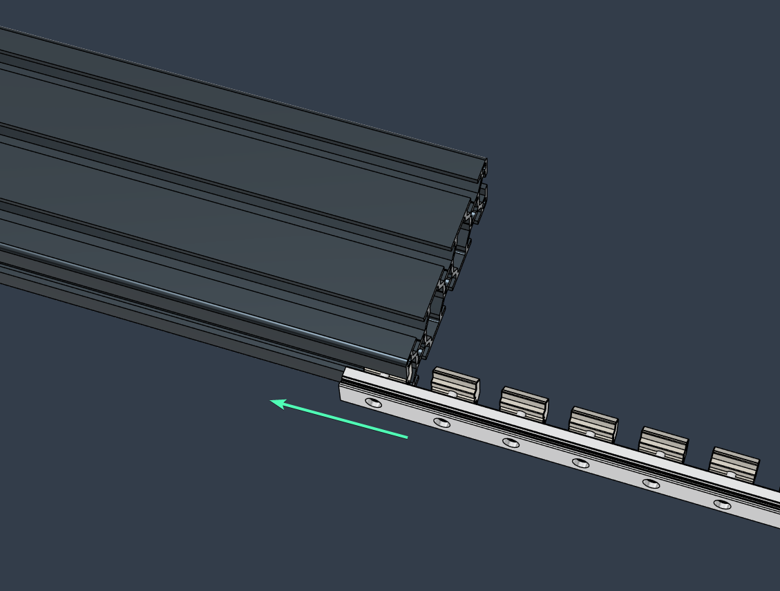
Note
The Linear Rails have to be inserted prior to closing access to the extrusions t-slot!
- Z Axis - Insert the rails before enclosing the frame with the top extrusion.
- Y Axis - Insert the rails before adding the motor mounts at the end of the extrusion.
- Attach the square t-nuts loosely to the rail then slide the rail into the extrusion t-slot.
Consult the CAD model for the number of screws and the spacing required for each rail type.
- Use the printed guides for alignment and spacing to position the rails
Mirror the exact steps, movements, and guide orientation on both sides to ensure a precise alignment between the matching rails.
- Tighten the screws to a consistent torque starting with the middle ones and progressing towards the edges
- Z Bearing Stack Assembly Diagram
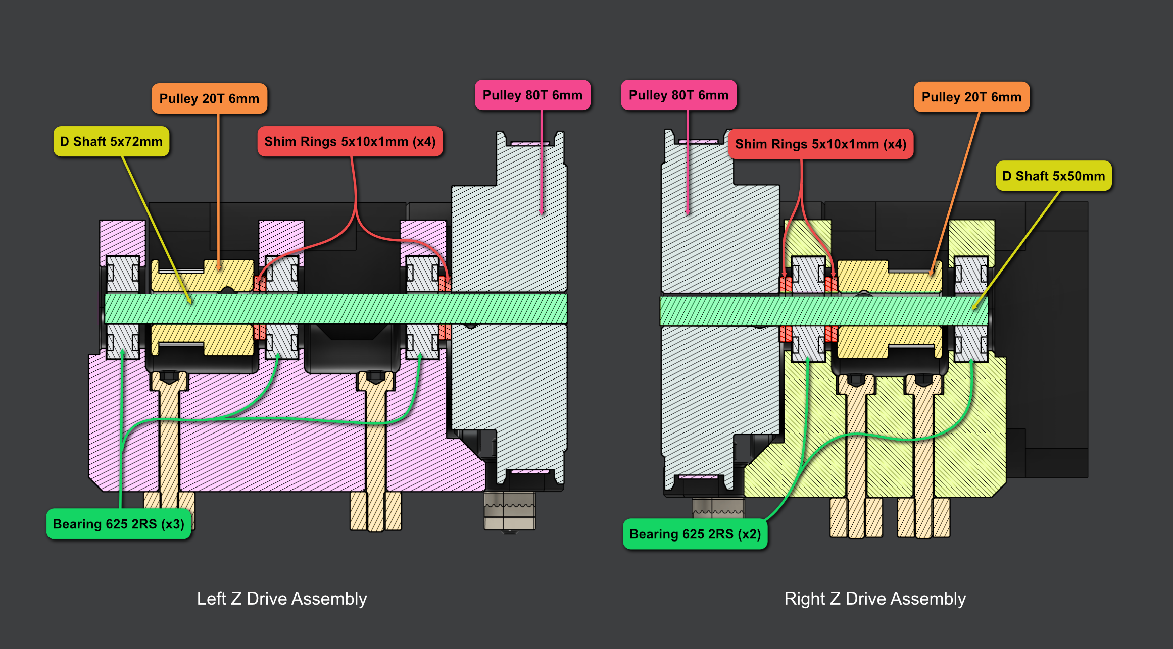
Left Z Drive Part List:
| Type | Item | Quantity |
|---|---|---|
| Motor | Nema 17 LDO-42STH40-1684AC | 1 |
| Pulley | 2GT-20T 6mm | 2 |
| Pulley | 80T 6mm | 1 |
| Bearing | 625 2RS | 3 |
| Shim | 10 x 5 x 1mm | 4 |
| Shaft | D Shape - 72mm x 5mm | 1 |
| Belt | 2mgt 6mm 188mm Closed Loop | 1 |
| Heat Insert | M3 Long 4.6x5.7 | 6 |
| T-Nut Drop In | 3030 - M3 | 3 |
| Washer | M4 9 x 0.5mm | 1 |
| Washer | M3 7x0.5mm | 6 |
| Screw Socket Head | M3 12mm | 4 |
| Screw Socket Head | M3 22mm | 2 |
| Screw Socket Head | M3 30mm | 6 |

Left Z Drive Assembly Video
z_left.mp4
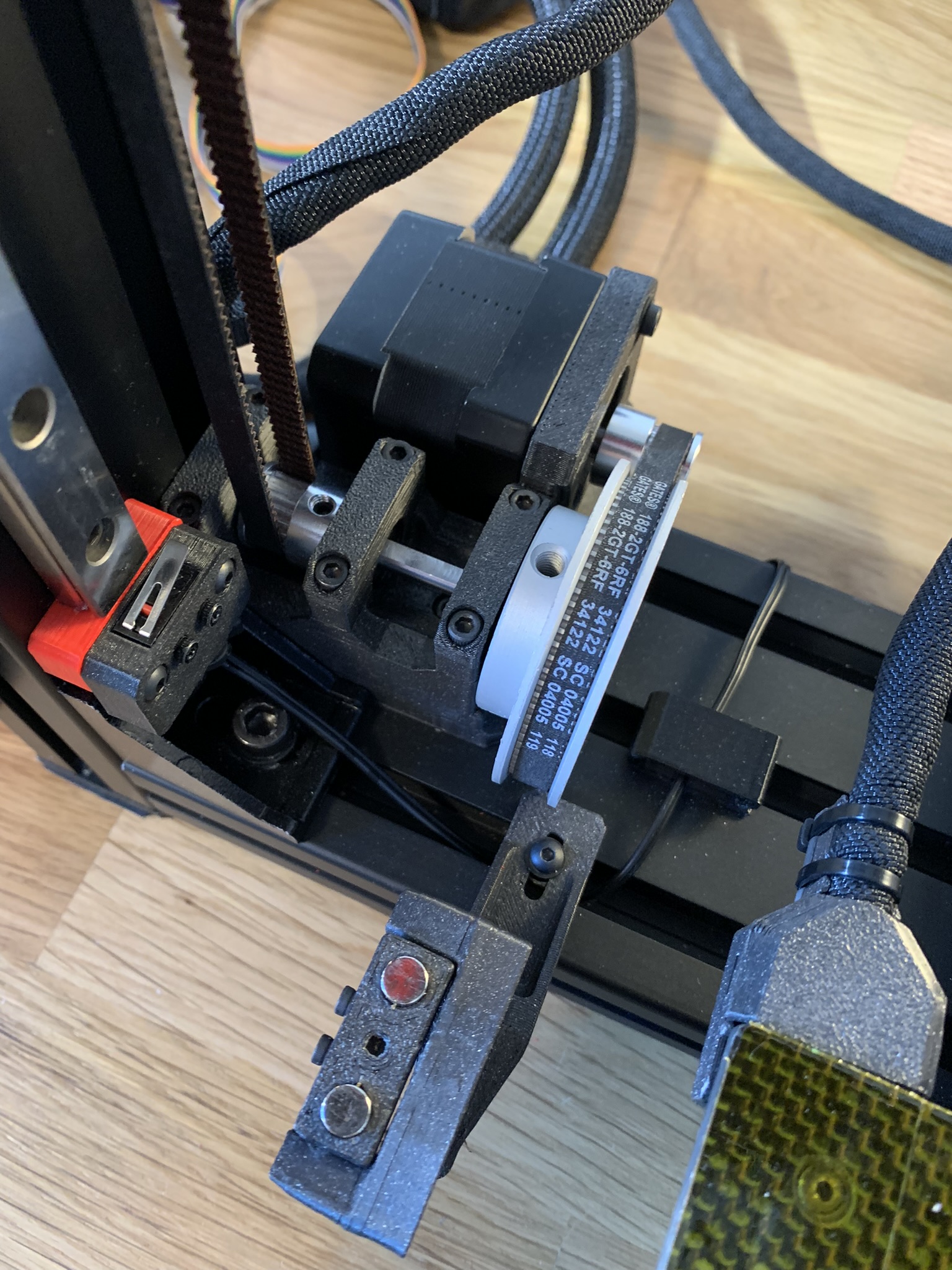
Right Z Drive Part List:
| Type | Item | Quantity |
|---|---|---|
| Motor | Nema 17 LDO-42STH40-1684AC | 1 |
| Pulley | 2GT-20T 6mm | 2 |
| Pulley | 80T 6mm | 1 |
| Bearing | 625 2RS | 2 |
| Shim | 10 x 5 x 1mm | 4 |
| Shaft | D Shape - 50mm x 5mm | 1 |
| Belt | 2mgt 6mm 188mm Closed Loop | 1 |
| Heat Insert | M3 Long 4.6x5.7 | 4 |
| T-Nut Drop In | 3030 - M3 | 3 |
| Washer | M4 9 x 0.5mm | 1 |
| Washer | M3 7x0.5mm | 6 |
| Screw Socket Head | M3 12mm | 4 |
| Screw Socket Head | M3 22mm | 2 |
| Screw Socket Head | M3 30mm | 4 |

Tip
Due to the nature of the design it is not possible to insert both T-nuts together.
The best strategy in this case is the following: attach the right motor mount without the highlighted T-nut, secure the right one and then slide the second T-nut into its final location from the side.

Right Z Drive Assembly Video
z.right.mp4
Z Tensioner Part List (x2)
| Type | Item | Quantity |
|---|---|---|
| Idler | Toothed 2GT-20T - 6mm | 1 |
| Shaft | Round 25mm x 5mm | 1 |
| Heat Insert | M3 Short 5x4 | 1 |
| T-Nut Square | 3030 - M3 | 3 |
| Hex Nut | M3 | 1 |
| Screw Button Head | M3 10mm | 2 |
| Screw Button Head | M3 20mm | 1 |
| Screw Socket Head | M3 14mm | 1 |
Note
The printed parts have markings to help alignment and installation.
Assembly Cross Section
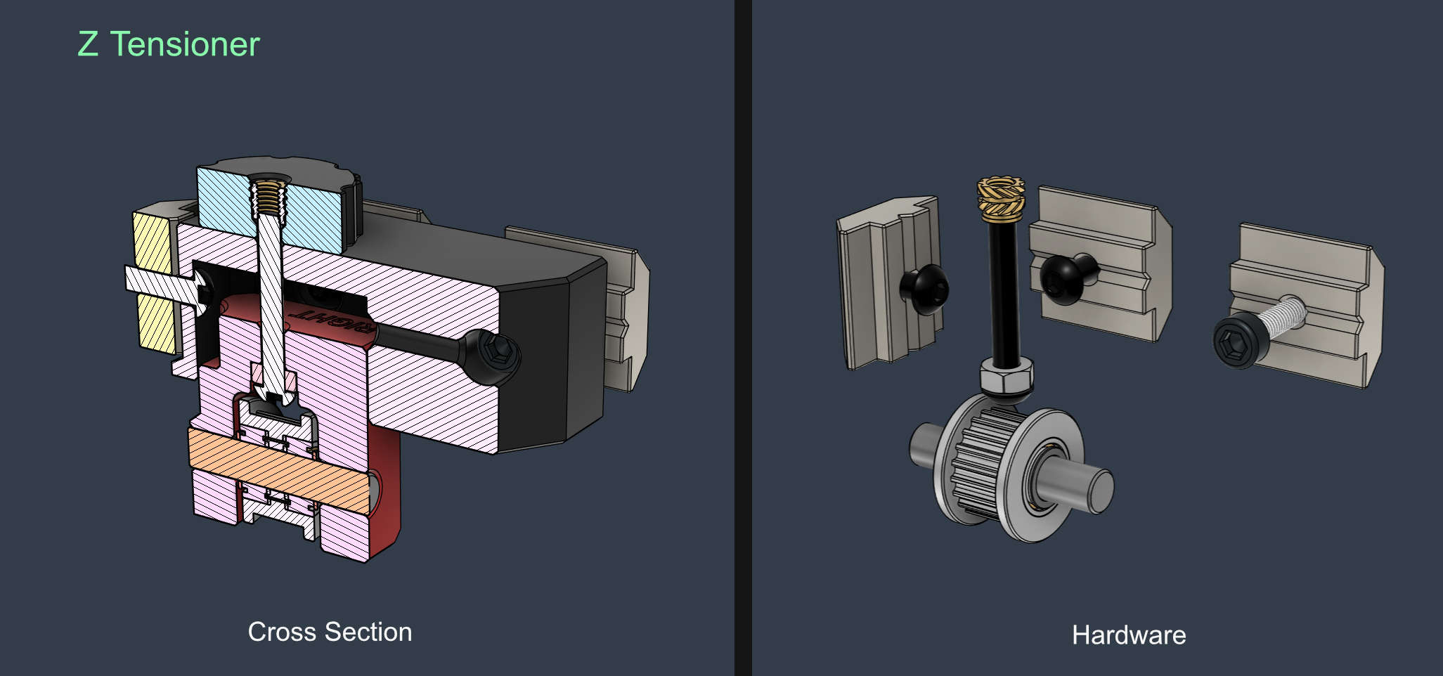

Tip
Add touch of glue to permanently lock the tensioning screw to the retaining hex nut.
Z Tensioner Assembly Video:
Note: mounts have been updated to use built-in spacers and don't require shims anymore.
Z.Tensioner.Left.v2.mp4
Animation by MakerMylo
| Type | Item | Quantity |
|---|---|---|
| Motor | LDO Nema_17_42STH48-2504AC | 1 |
| Pulley | 2GT-20T - for 9mm Belt | 1 |
| Idler | Toothed 2GT-20T - 9mm Belt - 5mm Bore | 1 |
| Shaft | Round 30mm x 5mm | 1 |
| Bearing | 625 2RS | 1 |
| Heat Insert | M3 Long 4.6x5.7 | 3 |
| Screw Button Head | M3 6mm | 1 |
| Screw Button Head | M8 16mm | 2 |
| Screw Socket Head | M3 30mm | 3 |
| Screw Socket Head | M3 35mm | 2 |
| Screw Socket Head | M3 45mm | 1 |
❗ Note:
- The linear rails have to be inserted before mounting the second Y motor mount.
- Make sure to have the required pre-loaded square nuts in place before closing access to the extrusion channels

Note: mounts have been updated to use built-in spacers and don't require shims anymore.
Y.Motor.Mount.mp4
Tip
For ease of installation, you can pre-insert the small screw that attaches the stepper and secure it temporarily with a hex nut. This is later tightened into the stepper motor though the side access hole.
If you missed this step, you can still insert it afterwards, but will require a bit of effort.
-
Insert the bearing into the mount
-
Attach the pulley to the shaft and leave a very small gap not to rub with the stepper motor's face
Do not add threadlocker to the front stepper motor since the pulley will require to be loosened for the AWD Sync procedure -
Make a mark with a Sharpie at the end of the motor shaft to indicate the flat D slot location. This will be needed for the next step.

- Insert the stepper with the pulley attached into the mount and bearing
- The front motor needs to have the pulley attached with the grub screws secured on the round/smooth side of the shaft. This is required to sync the AWD Y steppers.
Tip
-
You can print (or make) a 0.2mm thin washer that mates with the inner ring of the outer bearing to help with this.
If you de-flange the pulley as described in the Y Pulley Mod, the the end of the pulley can touch the bearing. -
If the bearing is too loose into the mount, you can attach a piece of tape to decrease the tolerance.
The same can be done on the stepper motor inner face plate to change the alignment if necessary.

An optional pulley mod is available here: Y-Pulley-Mod
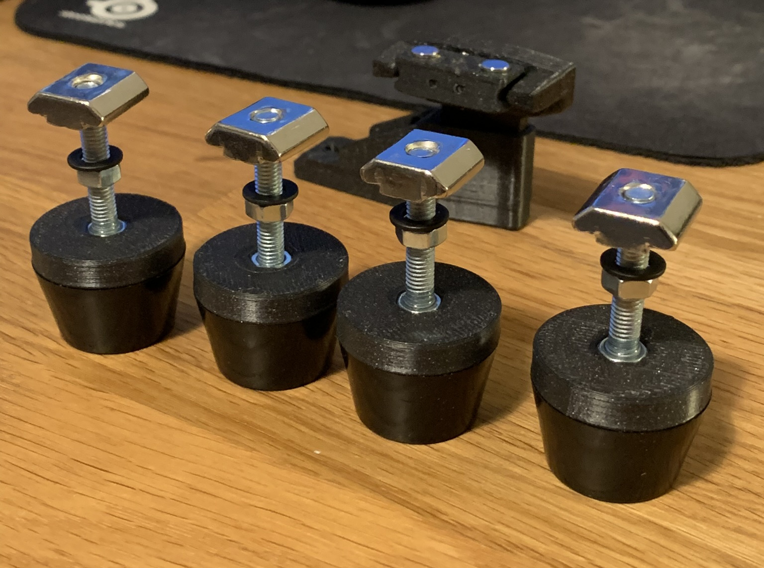
Part List (x4)
| Type | Item | Quantity |
|---|---|---|
| Foot | Rubber | 1 |
| T-Nut Square | 3030 - M5 | 1 |
| Washer | M5 14.8x1.2mm | 1 |
| Hex Nut | M5 | 2 |
| Screw Socket Head | M5 35mm | 1 |
🚸 The Square nuts in the assembly below have to be pre-loaded into the Y extrusion prior to attaching the Y stepper mounts.
The feet are then attached after installing the Y Motor Mounts.
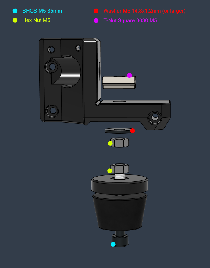
It is recommended to use larger "fender" type washers than the ones in the image below.
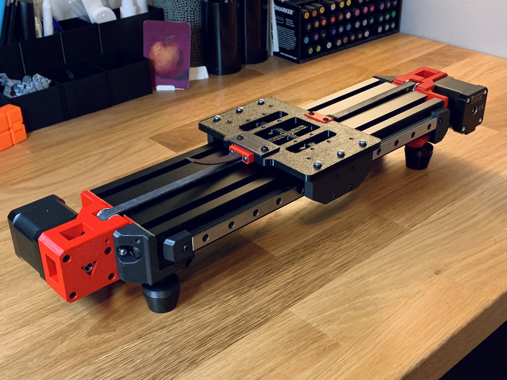
🚸 The recommended order of assembly is the following: Cart Mounts > Carriage > Belts > Bed

Cart Mount Part List (x2)
| Type | Item | Quantity |
|---|---|---|
| Heat Insert | M3 Long 4.6x5.7 | 3 |
| Washer | M3 7x0.5mm | 3 |
| Screw Button Head | M3 12mm | 4 |
| Screw Button Head | M3 30mm | 2 |
| Screw Button Head | M3 35mm | 1 |
-
Sand flat the mating side the Y cart mounts. Be careful to keep things flat and not change the 90 degree angle between the cart and the bed carriage planes. Try not to remove too much material.

- Attach the mounts to the Linear Rail Carts
- Push down while tightening to make sure they both have the same alignment against the top plane
- Place the carriage onto the cart mounts
- Make sure the tensioner side of the carriage faces the front motor mount. (The front is the side opposite to the Y endstop, and has a 25mm spacing between the end of the rail and the end of the extrusion)
- Tighten the CF carriage assembly to the mount by tensioning the screws progressively, while tightening the middle screw a bit more each time so that the carriage won't bow
- Move the carriage back and forth on the rails throughout the process to make sure the carriage and the mounts align themselves
- Proceed with the adjustment section below if the motion is not smooth and the carriage binds
Verify that the bed carriage moves smoothly by hand before installing the belt. If adjustments are needed proceed with the steps below:
- Loosen the three right side screws of the carriage to the cart mount just enough so things can self adjust (not totally loose or free). Move the carriage back and forth gently a few times.
- Tighten the right side again, as recommended in the first step
- Loosen the right side screws between the cart mount and the cart (linear rail bearing) just enough to self adjust. Move the carriage back and forth
- Tighten the mount back to the cart
- Repeat if needed
If the binding is still very noticeable, then you can try the following procedure:
- With the carriage and cart mounts tightened, loosen up all the right rail screws just enough so it can self adjust. Move the carriage front and back to align the linear rail to the opposite one.
- Tighten it back using the same amount of torque/turns for every screw and do not over tighten it.
- Move the cart and notice if there are individual binding spots. Adjust the torque of the screw in that location and see if the binding improves.
If severe binding started happening after installing the belt, try checking the following areas:
Note that some resistance from the stepper motors is expected, but nothing extreme
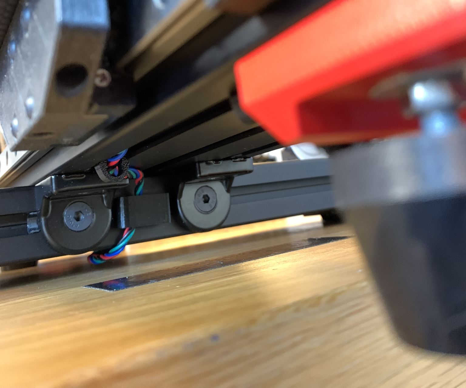
- Make sure that the belt path under the Y extrusion is not blocked by cable clamps, cables routed though it or any other objects
- Look under the carriage and see if the belt clamp screws are not biting into the extrusion. If the longer screws are used they will do so. Look for scratch marks on the top of the Y extrusion
- Make sure the Y stepper motor pulleys are not rubbing onto the stepper face or the bearings
- Try pushing the bearings away from the pulley with a screwdriver from the inside of the mount
- Try disconnecting both grub screws from the pulley and check the motion or nudge them a bit sideways
- If you need to remove the Y stepper motor for inspection, then loosen the belt and disconnect the four motor screws (The short screw is accessed with a hex key inserted though the side access hole, so you don't need to take apart the Y mounts). You might have to disconnect the pulley as well to make the removal easier
➡️ For the belt installation instructions please check out the Belt Installation Y Axis guide.
Note: In the images below, the Y axis has a printed test carriage installed instead of the real one.

Y Bracket Assembly (x4)
| Type | Item | Quantity |
|---|---|---|
| Bracket | Cast 90 Degree Corner 3030 - No tabs | 1 |
| T-Nut - Square | 3030 - M6 | 2 |
| Screw Countersunk | M6 14mm | 2 |
-
Measure the distance or use the printed positioning guide part (the Y extrusion is positioned 185mm from the outer Z pillars)
-
Leave a 1mm gap between the rear motor mount and the rear brackets to avoid any potential vibrations between parts.
- Ensure the Y-axis is exactly perpendicular (90 degrees) to the rest of the frame. This alignment directly affects the X/Y skew of the printed parts.

Bed Mount
| Type | Item | Quantity |
|---|---|---|
| Spacer | CFRP Spacer 10x4x3mm | 4 |
| Washer | M4 9 x 0.5mm | 8 |
| Hex Nut | M3 Locking | 4 |
| Screw Countersunk | M3 18mm | 3 |
| Screw Countersunk | M3 22mm | 1 |
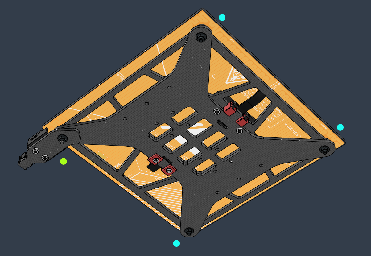

➡️ For the bed heater installation instructions please check the Bed Heater guide.
Caution
❗ Double check if there is enough clearance between the bed and the heater. Insert spacers or washers to increase the distance to a safe margin where there is no chance for the heater to rub with the screws.
If the screws come into contact with the bed heater, they will damage the polyimide layer, cause a short and start a fire!

- At minimum use one 3mm CF spacer + 1mm washer and check for clearance. For extra safety you can use 2x 3mm CF spacers.
![]()
Tip
- It is not recommended to perform the bed tramming procedure until everything under the bed is tested, set, and stable (such as the belt tension)
- Do not installing a bed surface until finishing the bed tramming procedure. If you do so you will have to cut access screw access holes into it
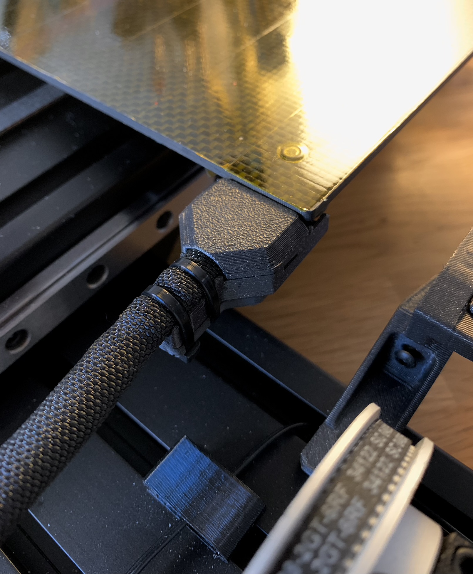
Cable Relief
| Type | Item | Quantity |
|---|---|---|
| Arm | CFRP Short Arm | 1 |
| Hex Nut | M3 | 2 |
| Screw Button Head | M3 6mm | 2 |
The Cable Relief printed piece is optional, and if you'd like, you can zip tie the cable loom directly to the CF relief part.
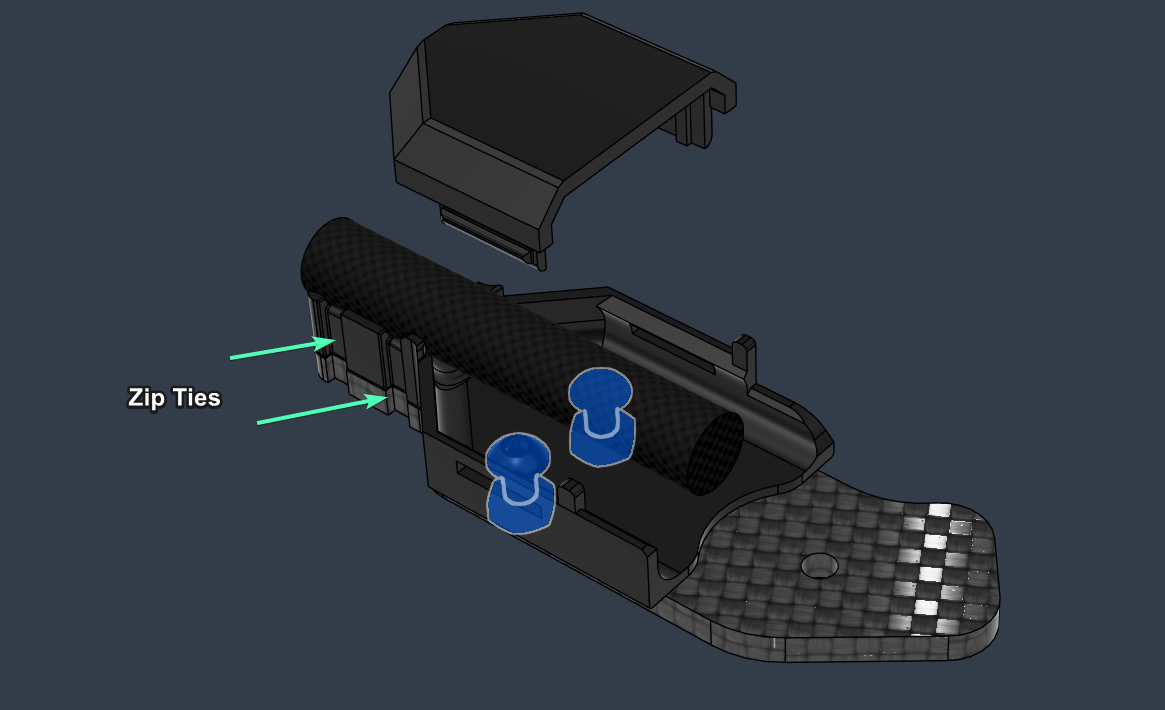
Tip: To help dampening stray resonances originating from the bed cable you can use a some PVC tape to cover the arm surface that contacts the bed carriage.
Note
Do not attach the toolhead belt tensioning module to the toolhead until after finishing assembling the X gantry.
The following steps are done off the printer
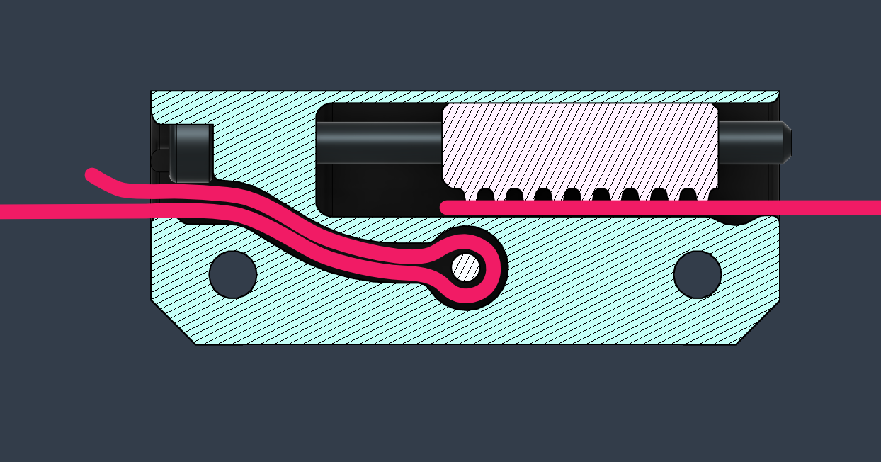
-
Prepare the Tensioner Block according to the instructions
-
Fold the belt and roughly measure or mark the length of the loop that would go inside the tensioner (the belt loop around the screw depicted in the image below). This will let you know when it's inserted all the way though.
-
If the belt insertion is difficult you can try coating the belt loop with water (and soap) to make it slide a bit easier. (Try it dry first)
-
Push it in using pliers if it doesn't go in easily. Be careful not to damage the belt
-
When you think you are done, you can insert a hex key into the hole and pull the belt to check if it's looped all the way into the cavity.
-
Insert the belt loop retaining screw that threads directly into the plastic
-
Leave the other side of the belt free until instructed to do otherwise
Tip
To make threading and setup process easier, it is recommended to carefully follow the mounting process described in the X Gantry section below.
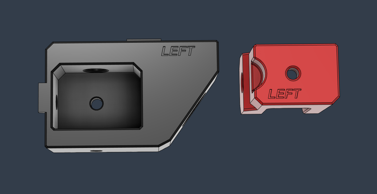
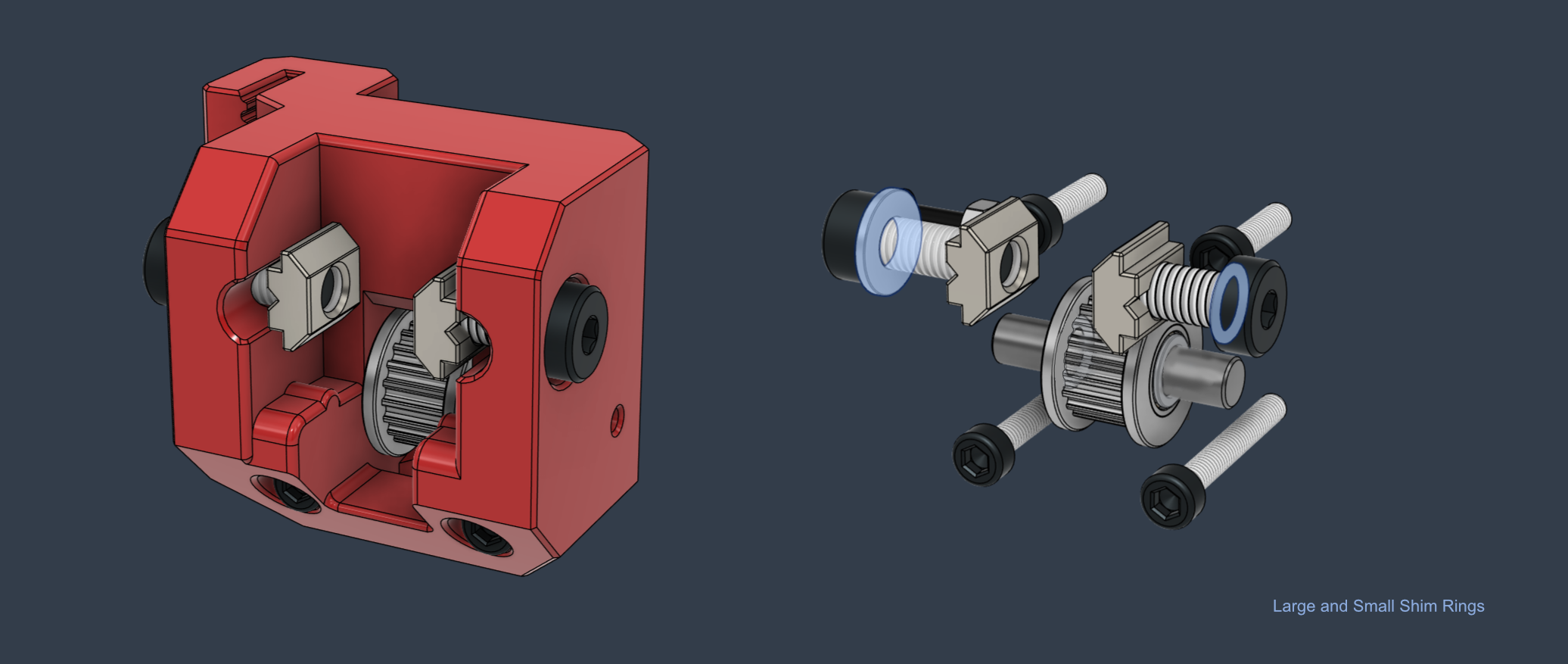
X Right Mount
| Type | Item | Quantity |
|---|---|---|
| Idler | Toothed for 2GT-20T - 6mm Belt | 1 |
| Shaft | Round 25mm x 5mm | 1 |
| Shim | 7 x 5 x 0.5mm | 1 |
| Shim | 10 x 5 x 1 | 1 |
| T-Nut Square | 2020 - M5 | 2 |
| Hex Nut | M3 | 1 |
| Screw Socket Head | M5 10mm Low Head | 1 |
| Screw Socket Head | M5 12mm | 1 |
| Screw Button Head | M3 12mm | 1 |
| Screw Socket Head | M3 12mm | 2 |
| Screw Socket Head | M3 22mm | 2 |
Assembly Steps
-
Insert the the idler shaft and the toothed idler
-
Thread the X belt in behind the idler
-
Screw the mount to the cart
-
Attach the belt
The M5 screws and the t-nuts depicted in the image below should be attached only when instructed during the final X gantry assembly procedure.
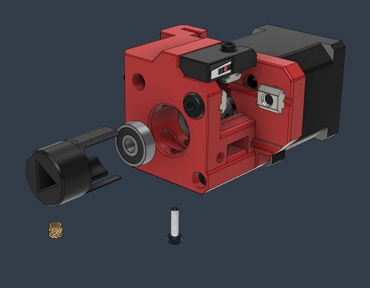
X Left Mount
| Type | Item | Quantity |
|---|---|---|
| Motor | LDO Nema_17_42STH48-2504AC | 1 |
| Pulley | 2GT-20T - For 6mm Belt | 1 |
| Bearing | 625 2RS | 1 |
| Heat Insert | M3 Short 5x4 | 1 |
| T-Nut - Square | 2020 - M5 | 2 |
| Hex Nut | M3 | 1 |
| Shim | 7 x 5 x 0.5mm | 1 |
| Shim | 10 x 5 x 1mm | 1 |
| Screw Socket Head | M3 14mm | 2 |
| Screw Socket Head | M3 12mm | 1 |
| Screw Button Head | M3 10mm | 3 |
| Screw Socket Head | M3 22mm | 1 |
| Screw Socket Head | M3 35mm | 2 |
| Screw Button Head | M3 12mm | 1 |
| Screw Socket Head | M5 10mm Low Head | 1 |
| Screw Socket Head | M5 12mm | 1 |
Assembly Steps
Note
Do not attach the X stepper motor before securing the Z belt to the left mount.
- Preload the four rail cart screws thought the round opening.
- Screw the mount to the cart by using the hex key access holes from the right side.
- Insert the hex nut into the side opening of the Z belt clamp
- Attach the Z belt and tighten the securing screw that goes into the hex nut.
- This screw is only intended for extra safety. Tensioning it at a high torque will crack the part.
- At this step of the process you might need to trim the Z belt precisely
- Insert the X belt loop into the mount
- Insert the stepper motor with the pulley while keeping the belt in the right place
- The X motor pulley requires a 1.7mm offset from the stepper face, with the middle of the belt sitting at a 13mm offset
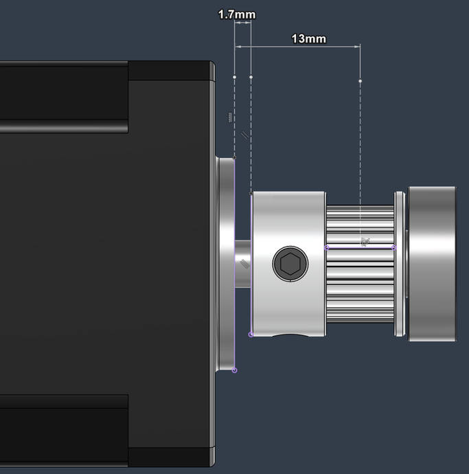
- Secure the screws of the stepper motor
- Temporarily insert the X extrusion into the mount and check for clearance between the pulley and the extrusion end
- Insert the bearing into the the Double Shear piece and place it into the mount while making sure it aligns with the bottom screw hole, it clears all the inner components, and the belt can travel freely. The bearing should not ride on the face of the pulley.
The M5 screws and the t-nuts depicted in the image below should be attached only when instructed during the final X gantry assembly procedure.

Note
The X Gantry requires a series of special steps to ensure a proper installation.
Please read them carefully.
Make sure to leave a gap in the following places so it permits movement during the Z tilt procedure.
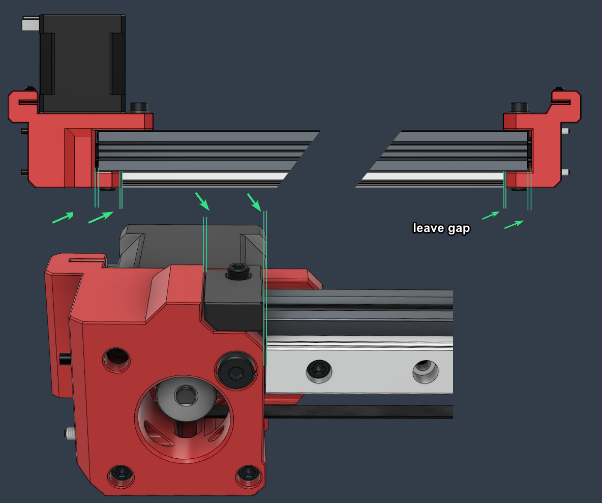
Assembly Steps
❗ It is recommended to have the Toolhead built and attached to the rail cart at this point and have it sitting on the dummy plastic rail holder
-
Preload the extrusion with two 2020 M5 square nuts on each side
-
Slide in the toolhead cart with the toolhead onto the rail, but do not attach it to the belt module
-
Insert the X extrusion into the mounts
-
Push the X belt into the bottom extrusion groove
-
Check the left and right spacings to make sure they are even
-
Press down the extrusion to ensure that it sits flat, then pull it towards the front so it's aligned against with mount's front wall
-
Loosely attach the screws. We want the extrusion to be able to tilt freely.
Tilting the printer towards the back might help the screws grab into the T-nuts. -
Attach the endstop mount. Leave a small gap on the left side to account for the extrusion tilt motion
-
Ensure that the screws sit on washers, and then tighten them in the following order: 1,4,2,3
- ❗ The front 1,2 screws require a medium-low torque, while the rear ones, 3, 4, require a low torque. This is to ensure that the gantry can tilt freely without putting a lot of stress on the mounts

Note
Please check the torque of the screws from time to time. It is possible that they will tighten themselves due to the gantry tilt motion.
- Insert the loose side of the belt into the Tensioner Block and make sure the recommended tension can be achieved using the tensioning screw.
The toothed insert piece has a very thin wall so make sure the heat insert doesn't bulge out sideways. Try reheating it and pushing against a flat surface. Eventually sand the surface until it's flat. Note: This part uses Heat Insert M3 Long - 4.6mm (D) x 5.7mm (L)
Tip
- A part with larger tolerances ( AC Toolhead Tensioner Inner - Tolerance ++.stl ) is included in the default Printer Parts.3mf project file This can be identified by the dot feature on the side

- Attach the Belt Module to the toolhead with two washers and two M3 40mm Button Head screws

When you have the printer setup and running, please repeat the following procedure:
- Run a Home and Z tilt procedure in Klipper (QD HOME TILT macro)
- After the Z tilt has been set and the gantry is aligned to the bed, keep the steppers engaged.
- Loosen the screws securing the X gantry and redo the extrusion setting by following the installation and tightening steps described above.
➡️ For more information please consult the Toolhead guide.
➡️ Pease refer to the following guide for setting up the belt tension: Belt Tension
Cart Stop (x6)
| Type | Item | Quantity |
|---|---|---|
| T-Nut Drop | 3030 - M3 | 1 |
| Screw Socket Head | M3 12mm | 1 |
X Endstop
| Type | Item | Quantity |
|---|---|---|
| MicroSwitch | With Lever | 1 |
| T-Nut Drop | 2020 - M3 | 1 |
| Screw Socket Head | M3 12mm | 1 |
Y Endstop
| Type | Item | Quantity |
|---|---|---|
| MicroSwitch | With Lever | 1 |
| T-Nut Drop | 3030 - M3 | 1 |
| Screw Button Head | M2 8mm | 2 |
| Screw Socket Head | M3 12mm | 1 |
Z Endstop
| Type | Item | Quantity |
|---|---|---|
| MicroSwitch | With Lever | 1 |
| Heat Insert | M3 Short 5x4 | 2 |
| T-Nut Drop | 3030 - M3 | 1 |
| Washer | M3 7x0.5mm | 2 |
| Screw Button Head | M2 8mm | 2 |
| Screw Button Head | M3 12mm | 2 |
| Screw Socket Head | M3 12mm | 1 |
Microswitch installation:
Note: The printed microswitch mounts have sacrificial bridges on the backside M2 screw holes. Break those before installation.
- Test if the microswitch fits into the mount. If stuck, there are backside holes built into the mounts to push the microswitch back out.
- Insert two cables though the mount channels (try threading them from either side, whichever is easier depending on the mount)
- Solder the outside pins of the microswitch to the cable. The polarity doesn't matter since the microswitch just closes or opens the circuit
- Insert the microswitch into the mount and attach the M2 screws (if the mount has holes and your microswitch holes are 2mm diameter)
- Zip tie the cable to the mount
- Test the continuity with a multimeter to verify that the microswitch is working properly
- Cut the wires to length and crimp them

Probe Dock
| Type | Item | Quantity |
|---|---|---|
| Magnet | 6x3mm | 4 |
| T-Nut Drop In | 3030 - M3 | 1 |
| Screw Button Head | M3 12mm | 1 |
| Washer | M3 7x0.5mm | 1 |
| Hex Nut | M3 | 1 |
| Screw Button Head | M3 6mm | 1 |
The following steps will ensure that the probe dock is properly set to work with the default parameters set in the configuration (quickdrawprobe.cfg)
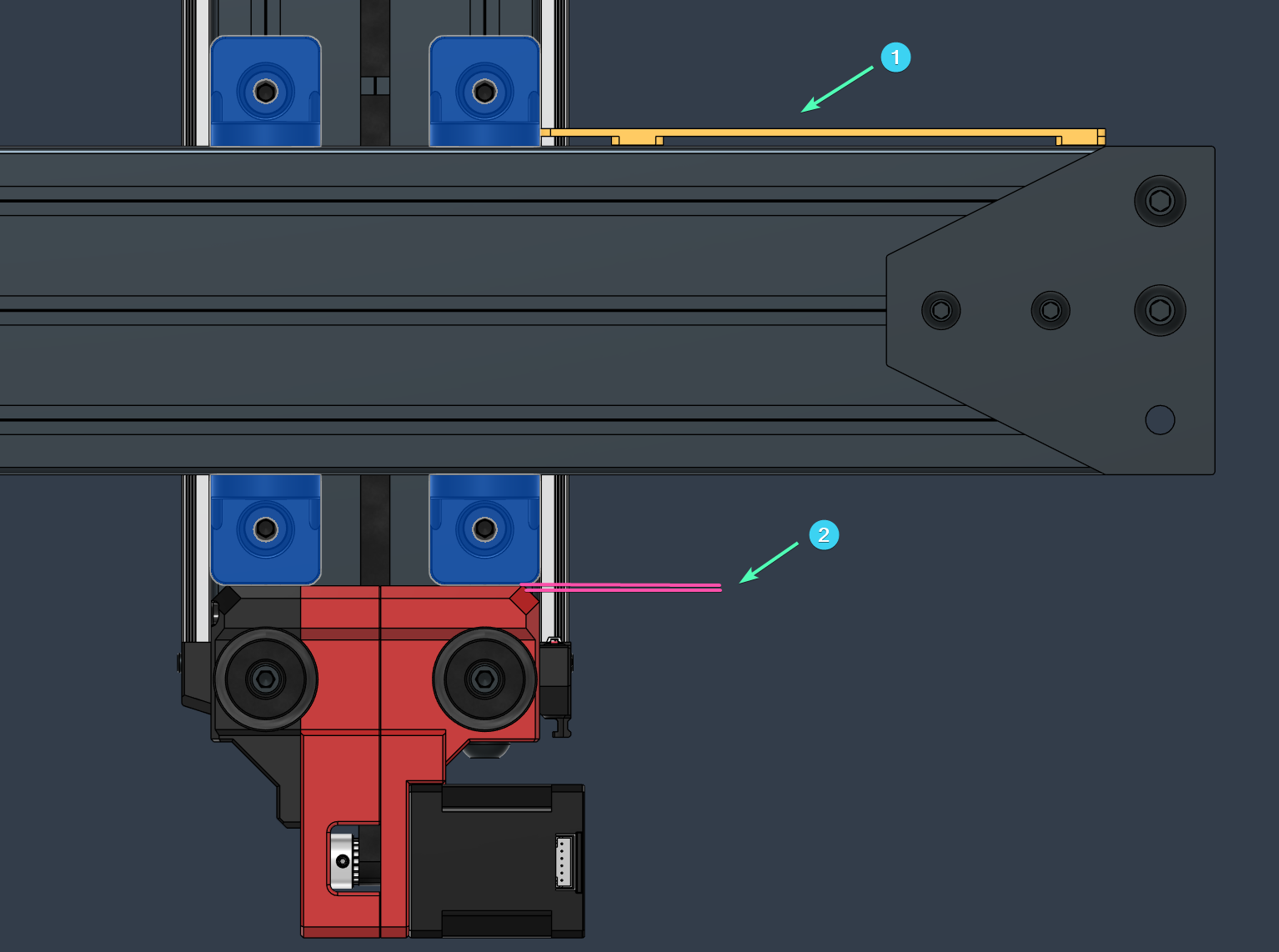
- Install the probe dock 97mm from the Z pillar (1)
- Move the bed fully towards the back of the printer
- Move the toolhead over the probe location, and lower the X gantry until the point where it touches the Z endswitch (3)
- For UHF hotends the adjustable Z endstop needs to be lifted to the high position.
- When triggering the endstop, the hotend nozzle has to be below the bed surface otherwise the Z endswitch will be triggered during printing
- Adjust the dock height (2) so that the probe magnets engage with the Toolhead dock (4)
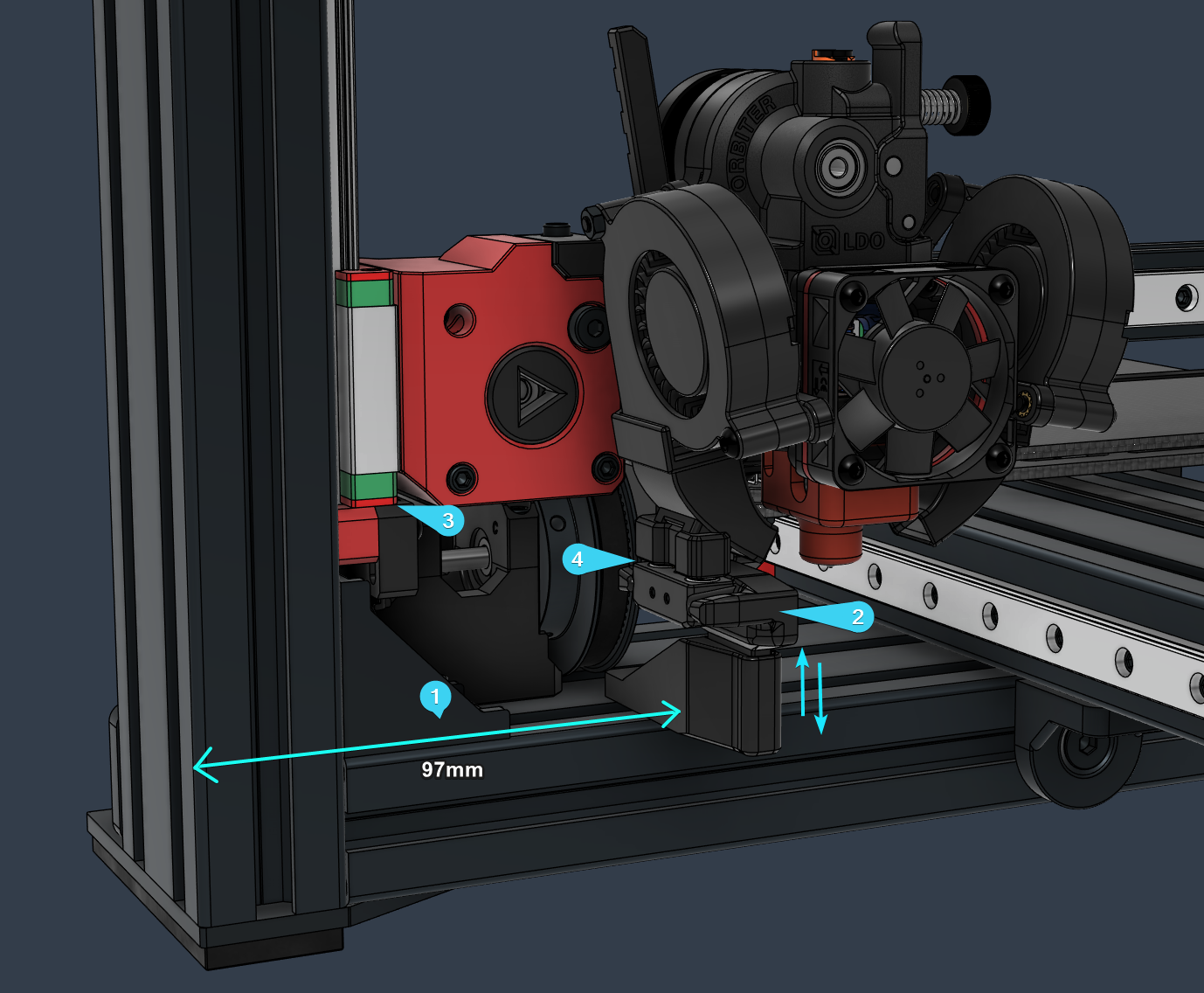
- Please see the following guide for the Probe installation on the Toolhead side: Toolhead#probe
➡️ Please check the Printer CAD assembly for the latest recommended cable routing setup. The addition of the breakout box changed things a bit.
- The printed Cable Clips with the built in T-Nuts are set in place by inserting then into the extrusion channel and then twisting them into the final position


If you reached this stage in your build congratulations and many thanks for your patience and perseverance! 🎉
I hope the Stinger serves you well, and you'll enjoy using it for your projects. Before obsessing over fine details I recommend going though some daily prints, having fun with it, and maybe not jumping straight away into exploring the absolute limits of the machine until gaining more experience with it :)
As a next step, I recommend performing the following checks: Tuning - Post Build Checks
and also getting familiar with the following guides:
Configurations, macros, themes and profiles can be found here:
https://github.com/lhndo/LH-Stinger/tree/main/Config
https://github.com/lhndo/LH-Stinger/tree/main/KITS/FYSETC/Klipper_Config_FYSETC