-
-
Notifications
You must be signed in to change notification settings - Fork 22
Toolhead
undoz edited this page Sep 25, 2024
·
35 revisions
Contents:

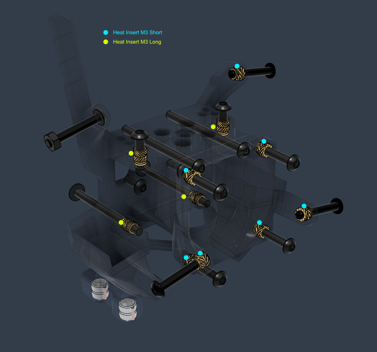
Toolhead Part List:
| Type | Item | Quantity |
|---|---|---|
| Cooling Fan | Radial 5015 | 2 |
| Cooling Fan | Axial 4010 | 2 |
| Hotend | Phaetus Dragon HF | 1 |
| Extruder | Orbiter V2.0 | 1 |
| Heat Insert | M3 Long 4.6x5.7 | 4 |
| Heat Insert | M3 Short 5x4 | 7 |
| Nut Hex | M3 | 1 |
| Screw Button Head | M3 12mm | 2 |
| Screw Button Head | M3 16mm | 4 |
| Screw Button Head | M3 20mm | 4 |
| Screw Button Head | M3 40mm | 4 |
| Screw Button Head | M3 8mm | 2 |
| Washer | M3 7x0.5mm | 2 |

- The heated insert in this location has to be done with the iron sideways at 90°
- The hole should self align the insert, but if there are issues with that, you can heat up the brass part and then insert a screw though the backside to fix the alignment.

Toolhead Assembly Video:
toolhead.mp4
Tensioner Block Part List:
| Type | Item | Quantity |
|---|---|---|
| Heat Insert | M3 Long 4.6x5.7 | 3 |
| Heat Insert | M3 Short 5x4 | 2 |
| Screw Button Head | M3 6mm | 2 |
| Screw Countersunk | M3 16mm | 1 |
| Screw Socket Head | M3 12mm | 3 |
| Screw Socket Head | M3 40mm | 1 |

- Sand flat the mating area of the tensioner block

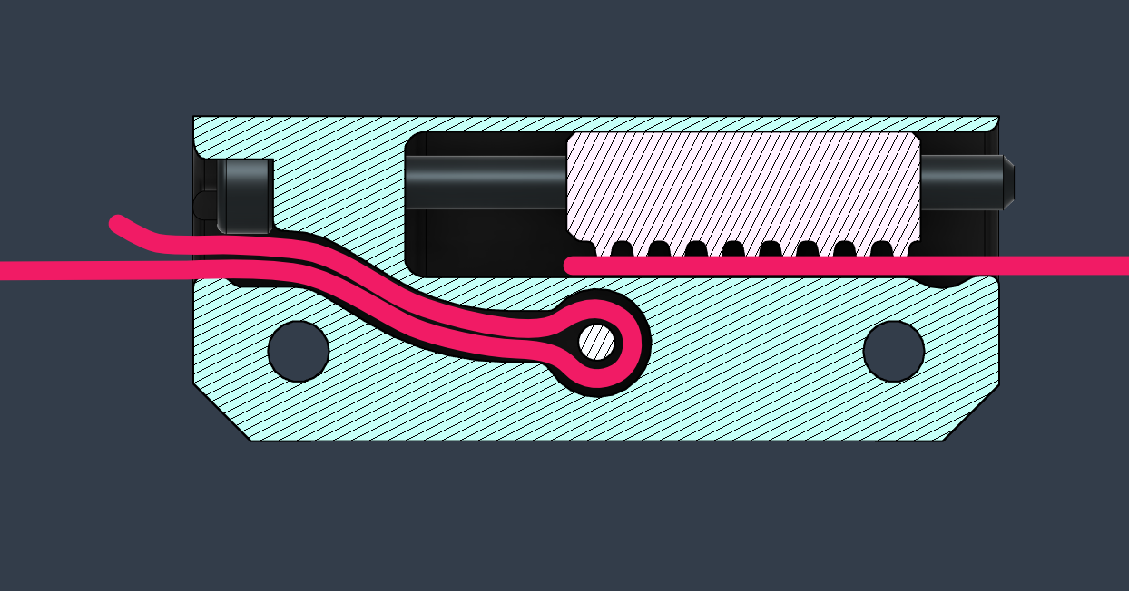
- If you have difficulties inserting the belt loop on the left side of the belt tensioner, then try wetting the belt, or dipping it in soapy water to decrease friction, and push the belt in with a pair of pliers.


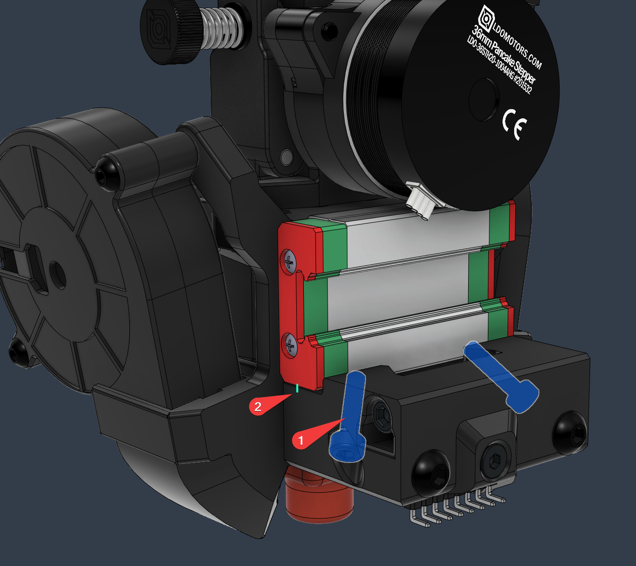
- The two side screws are used to add extra stiffness to the assembly by clamping the linear rail cart.
This solution showed a considerable improvement in resonance testing.
- Add a threadlocker to the screws (1)
- Tighten the screws into the block while keeping an eye to the side gap between the cart and the toolhead (2).
The screws should be snug against the cart, but not so they would bend the printed part (too much 😃 )

QuickDraw Probe Part List:
| Type | Item | Quantity |
|---|---|---|
| Microswitch | Omron D2F-5 | 1 |
| Magnet | 6x3 mm | 2 |
| Screw Cap Head | M2.5 8mm | 2 |
- Get familiar with the orientation of the switch and the screws by checking the taper of the side slots
- Measure the magnets (6x3mm) and the inner diameter of the magnet sockets
- Use a 6mm drill bit to clear up the holes, or reprint the part using shrink compensation if needed
- Cut the middle pin of the microswitch and insert it into the printed body
- Push the microswitch pins into the adjacent wall so there's enough room for the magnet
- Make sure the polarity of the magnets match between the toolhead dock and the probe
- The polarity between the right and left side doesn't as matter much, but it is usually recommended to have them opposite
- If you do so, then make absolutely sure the probe is oriented in the correct way, with the screws facing right, and the microswitch button closer to the front of the printer, and it matches the ones installed inside the toolhead dock
- Insert the magnets fully and make sure they are absolutely level
- Use a multimeter to check the switch and the continuity of the magnets when done
Toolhead Part List:
| Type | Item | Quantity |
|---|---|---|
| Magnet | 6x3 mm | 4 |
| Wire | Endstop cable | 1 |
- Clean up any excess plastic from the holes and check the diameter before inserting the magnets. A 6mm drill bit can be helpful in this case
- Getting the magnets stuck in the wrong place during insertion is not easiest thing to deal with
- In case this happens and you can absolutely not remove or insert them fully, try heating up the magnet with a soldering iron and then push it in place white supporting the printed part
- Strip a slightly longer section of wire and twist the strands together
- Insert the cable in the dock and out of the magnet holes
- Push the magnets in the holes of the dock while keeping the cable on the side.
- Make sure the the polarity of the magnets matches the probe if you assembled that one first. If not, then it is usually recommended to have them opposite between each side, but it doesn't matter much
- The magnets should be absolutely level and protrude less than 1mm from the dock
- Trim the excess cable
Tip
If the magnets are too loose then you can insert another dummy wire on the side of wall of the hole to secure it better

- When done. measure the continuity between the magnet and the cable at the other end
- The Probe wire is inserted though the following holes and secured with a zip cable tie

Toolhead
- ~12.30 mm for Orbiter 2.0 and Dragon HF
- Flat cut on the hotend side, tapered bore on the extruder side
Reverse Bowden
- 60 cm
Note: The fan cables are glued to the outside face of the blower fans
