FYSETC Kit
Ready made Orca slicer Plates are available: https://github.com/lhndo/LH-Stinger/tree/main/STL
Select the FYSETC labeled plates and omit the parts which these replace.

If you prefer to download the individual parts, then the following ones are required to match the component configuration of the FYSETC kit:
-
Toolhead: Toolhead Dragon UHF + Sherpa Mini
-
Aux Fan: Flap UHF x2
-
Ebox: FYSETC Spider Mount
Firmware flashing instructions: FYSETC S3 H7 Firmware Guide
Reference Firmware Settings:
[*] Enable extra low-level configuration options
   Micro-controller Architecture (STMicroelectronics STM32)
   Processor model (STM32H723)
   Bootloader offset (No bootloader)
   Clock Reference (25 Mhz crystal)
   Communication interface (USB (on PA11/PA12)) *
   USB ids (leave default)
() GPIO pins to set at micro-controller startup
* or Serial Communication interface (USART1 PA10/PA9) for direct UART to Pi connection (USB recommended)
For flashing the ADXL probe please follow these instructions: https://github.com/FYSETC/Nozzle-Input-Shaper/issues/9
🚸 It is recommended to use the FYSETC Kit configuration files from the LH Stinger Repository linked below.
These are up to date and compatible with the latest LH Stinger changes.
📘 This configuration is set up to include all the changes mentioned in the Issues section below
https://github.com/lhndo/LH-Stinger/tree/main/KITS/FYSETC/Klipper_Config_FYSETC
Important
Please ensure you read the Safety section of this guide.
Disclaimer
This is a DIY (Do-It-Yourself) experimental project. This information is provided "as is" without any guarantees or warranty, and is not certified for any commercial or critical applications. Use it at your own risk. The creator assumes no liability for damages or injuries resulting from its use, including but not limited to fire, electric shock, personal injury or property damage. By using this you agree to the terms of this disclaimer.
Stepper Mapping:
| Driver | Motor |
|---|---|
| X | X Motor |
| Y | Y Rear Motor |
| Y1 | Y Front Motor |
| Z | Z Left Motor |
| Z1 | Z Right motor |
| E | Extruder Motor |
Wiring Diagram:
🚸 The following diagrams include the fixes noted in the Issues section below, and are compatible with the configuration found on this repository.

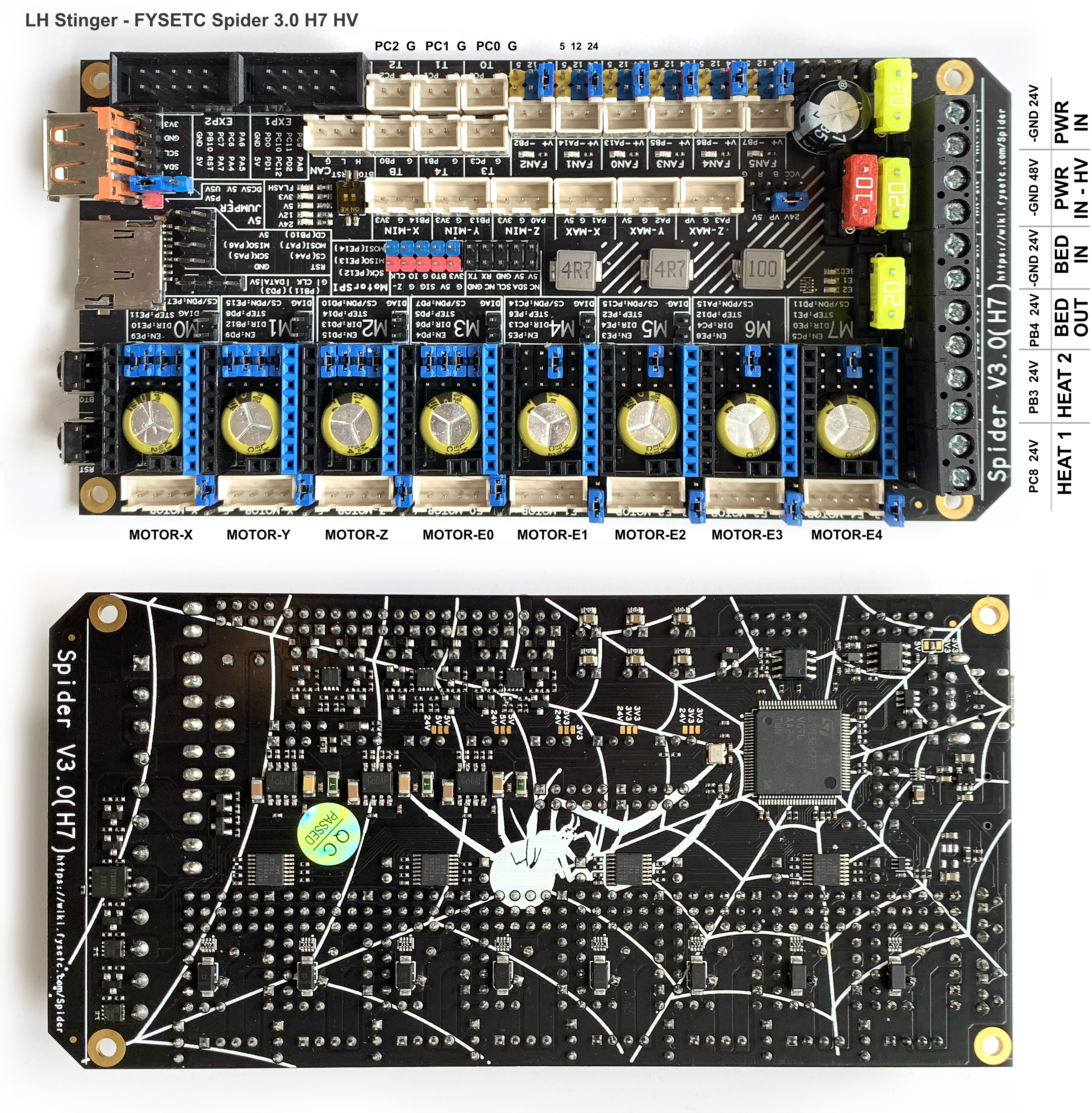
LH Stinger - FYSETC Spider 3.0 H7 HV
https://github.com/FYSETC/FYSETC-SPIDER-H7

LHS Breakbeat


FYSETC Breakout Wiring Harness

-
⚠️ It is advised to not install the supplied PEI sheet due to the difficulty of removing the adhesive! Printing on the bare CF plate works well with or without a bit of glue. It is recommended to try this method, at least in the beginning. -
Do not attach any bed surface sheet until you are absolutely sure you don't have to disassemble the bed soon enough, otherwise you will have to cut access holes for the screws.
- Reverse the motor orientation so that the cables point downwards.

- Check if the mating of the bottom surface is flush. Loosen the motor mount screws, set the extruder on a flat surface and tighten everything back up.
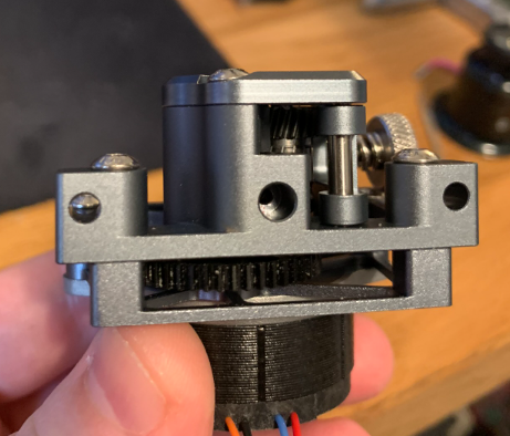
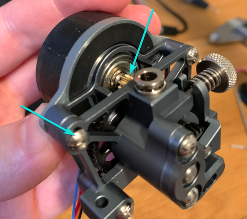
- Adjust the gearing backlash by unscrewing the left side of the motor and gently set the 8T gear against the POM gear.
- For ease of cable routing, on the EBox side, instead of using the E plug from the sensor harness you can use the X1 plug from the motor harness to connect the E motor driver.
Then on the breakout board side you connect the E motor cable from the toolhead to the X1 port.
- Due to the thickness of the heater wire sleeves it is recommended to mount the Dragon UHF hotend at 90 degrees for easier cable routing
 Image by Aavikkokettu
- For UHF hotend variants it is recommended to use the Aux Aero diverter from User Mods This will provide better hotend shielding and part cooling https://github.com/lhndo/LH-Stinger/tree/main/User_Mods/Toolhead/UHF_AUX_Aero_Diverter

The Fysetc Nozzle ADXL is meant to be temporarily nozzle mounted only during the X axis resonance testing procedure.
When testing the Y axis, it is mounted on the bed with the following mount: FYSETC Nozzle ADXL Bed Mount, which is also included in the Other Parts.3mf plate.
The bed mount is then secured with a thin double sided mounting tape thinner than 0.1mm and the adxl PCB is secured with a spare V6 nozzle screwed into the mount.
More details can be found here: https://github.com/lhndo/LH-Stinger/wiki/Tuning#resonance-testing
-
The ADXL probe firmware needs to be updated by follow these instructions: https://github.com/FYSETC/Nozzle-Input-Shaper/issues/9
-
The adxl.cfg include needs to be un-commented from the printer.cfg configuration.
-
The serial address from adxl.cfg needs to be updated to match your device
The following list keeps track of BOM changes or differences from the main project since the FYSETC V1 Kit release. These differences are being communicated back to FYSETC.
The Kit includes extra fasteners but you might need to supplement with a few of your own.
Corrections:
- Corrected 6x3m Magnets amount from 12 to 16pcs
- M3 4.6x7 Heat Inserts are provided instead of M3 4.6x5.7 (Heat Insert M3 Long) (39 pcs total)
- Bag is also mislabeled as Threaded Insert Short instead of Threaded Insert Long
Additions :
- +30pcs M3 4x5 Heat Insert Short (100 pcs total)
- +12pcs M3 10mm FHCS (35 pcs total)
🔶 Please go though your FYSETC KIT content and verify the state of the following reported issues:
An error was found in the Breakbeat Wiring Harness specifications V1.0, which had the 2 Pin JST HX Fan connectors polarity flipped.
This was due to the fact that Fysetc boards use reversed fan polarity and the harness ended up in a "double flip" situation when it's only meant as a passive passthrough
Fix:
"Sensor" Wiring Harness (EBox side):
- De-pin the 2 Pin JST XH connectors with the following labels and flip the wires to match the orientation in the image below:
Fan H , Fan P (Not Aux)

How to Remove and swap leads for JST XH 2.54 Terminal:
https://www.youtube.com/watch?v=q8tU_NEZK9g
Endstop microswitches
The endstop wires have to be routed first though the endstop case.

Fix:
- Remove the crimps and thread the cable though the endstop mounts. Re-crimp after mounting the microswitch to the mount and measuring the required cable length.
AGND jumper not set on the LHS Breakbeat board
🚸 Please read Issue 1008 as a follow-up.
The AGDN pins provide ground to the thermistors. It is an optional input that allows bringing a filtered analog ground to the sensors. If that is not provided, then the pins should be bridged.

Fix:
- Install a jumper to bridge the two AGND pins
Z Feet Pads
The choice of a hard rubber material for the Z Feet Pads is not ideal for the intended weight distribution and dampening. This will most likely affect the resonance test results and input shaping performance by minimizing the decoupling of the axis.

Fix:
- Replace the feet with a hard foam material which allows for some compression
Z Motor Cables
The Z motors have a different pinout for the coils than the X and Y motors, and require a different wiring order

Fix:
Flip the middle two wires to match the orientation in the picture above. Perform this procedure on both Z and Z1 cables
- Pull the cable tag down
- Lift the plastic tabs on the middle two pins with some tweezers (one at a time)
- Pull the middle two wires
- Push down on the plastic tabs to revert to their position and retain the wires better
- Reinsert the wires in the orientation matching the picture above
Y Stop Cable 5V Source
The Y Stop cable also functions as a 5V power supply to the breakout board. On the Spider, this is found on the Y_MAX port, Y_MIN supplying only 3.3V

Fix:
- Swap the Y connector with the F Sens connector, such as the Y Stop cable is connected to Y_MAX.
- Make sure the pins match in the configuration (default configuration will be provided for this wiring setup)
Unreliable Hotend Thermistor Reading
The PWM value of the hotend heater is seen to pulsate between 0-100% which has been traced back to the PT1000 thermistor ground supply.
This is due to a mismatch in ground levels between the PSU and the mainboard
Fix:
This issue can be solved by sourcing ground from a different place, closer to the MCU point of reference.
- Cut the fork terminal off the DC -v "Ground" wire

- Solder splice an AWG 22/24 cable extension and terminate that with a JST XH crimp and connector

- Plug the JST connector as shown

Note: if you experience other issues in regards to maintaining the hotend heating power at very high fan values, then it's recommended to install the AUX Fan Aero Diverter. This is required due to the large footprint of the heater block exposed to cooling.
Printer Cable Lengths
The cables between the printer and the breakout board are not pre-cut to optimal lengths
Fix:
- Please consult the Breakout Box - Printer Cable Lengths section for the optimal cable lengths.
- It is advised to leave anything related to the toolhead and bed in its existing form for now, and only shorten the Motor, Endstops and Aux Fan cables.
PWM/RGB Connector
The PWM wire is not set into the appropriate place
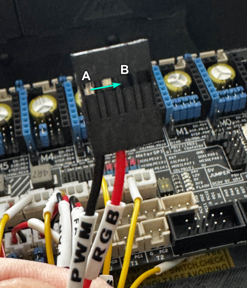
Fix:
- De-pin the PWM wire (A) and connect it into the middle slot next to the RGB one (B).
