-
-
Notifications
You must be signed in to change notification settings - Fork 22
Ebox
Important
Please ensure you read the Safety section of this guide.
Disclaimer
This is a DIY (Do-It-Yourself) experimental project. This information is provided "as is" without any guarantees or warranty, and is not certified for any commercial or critical applications. Use it at your own risk. The creator assumes no liability for damages or injuries resulting from its use, including but not limited to fire, electric shock, personal injury or property damage. By using this you agree to the terms of this disclaimer.


Note: The WAGO connector holders are attached with strong double sided mounting tape.
Stepper Jumpers:
- The steppers (TMC2240) are set up in the default configurations with all four jumpers set to SPI mode
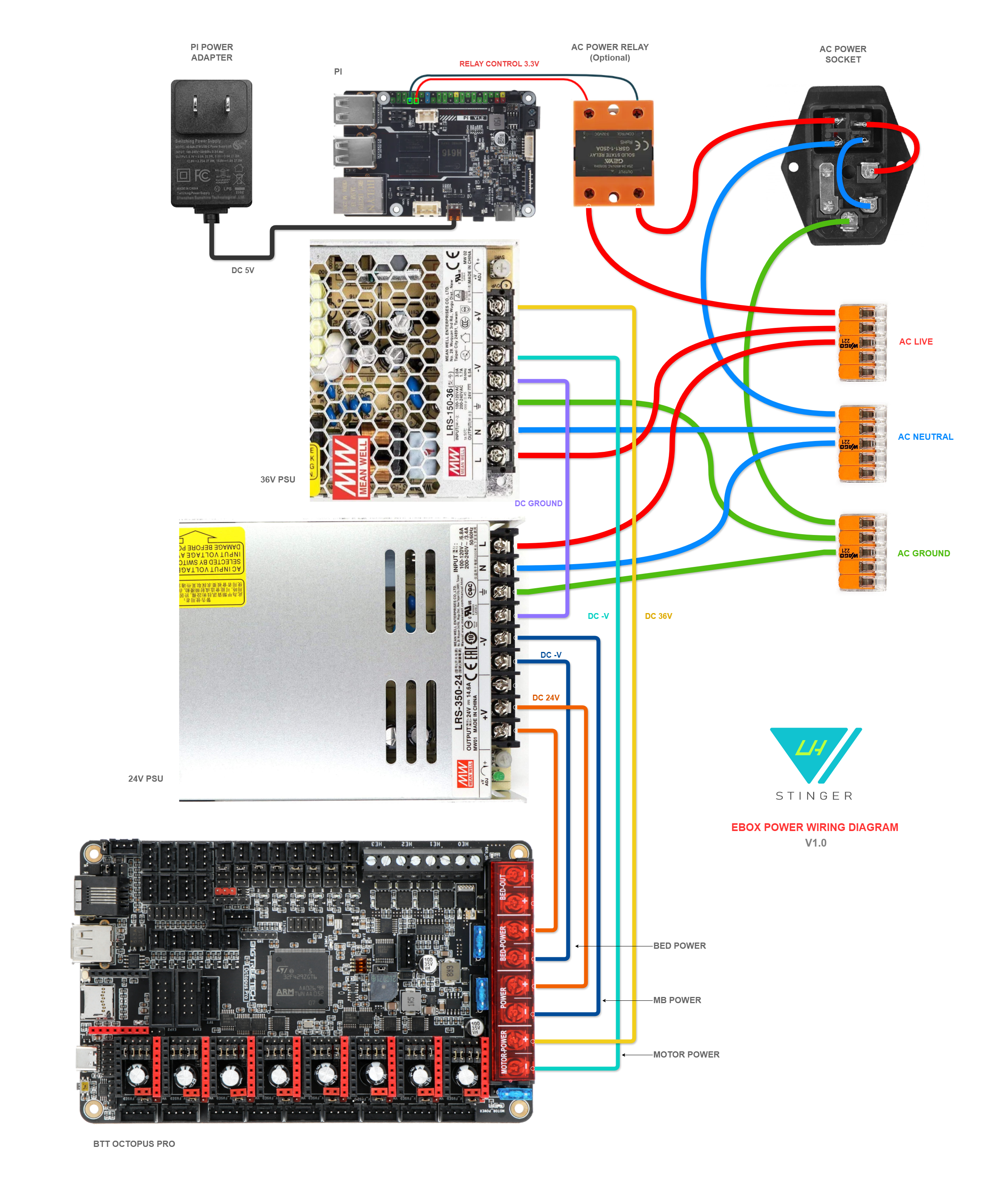
- X, Y and Y1 drivers have their power jumper set to the Motor Pwr (36V) position
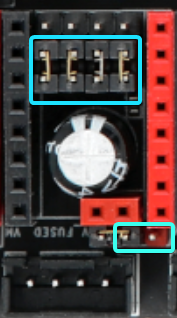
Stepper Mapping:
| Driver | Motor |
|---|---|
| X | X Motor |
| Y | Y Rear Motor |
| Y1 | Y Front Motor |
| Z | Z Left Motor |
| Z1 | Z Right motor |
| E | Extruder Motor |
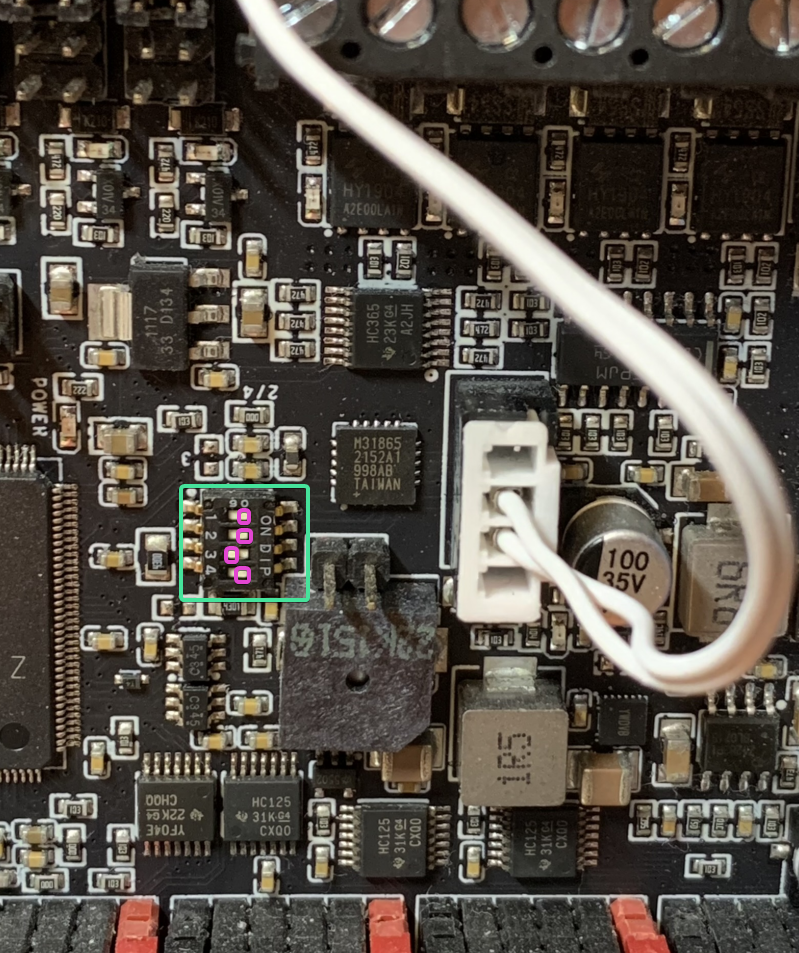
MAX31865:
For the 2 wire PT1000 hotend thermistor connected to the Octopus Pro though the MAX31865 IC you need to set the dip switches to the following positions:
1 ON | 2 ON | 3 OFF | 4 ON
Main Components List:
| Type | Item | Quantity |
|---|---|---|
| Mainboard | Octopus Pro v1.1 h723 | 1 |
| Host | BTT Pi v1.2 | 1 |
| Fan | Axial 6025 | 2 |
| PSU | Meanwell LSR-350-24V | 1 |
| PSU | Meanwell LRS-150-36V | 1 |
| Connector | WAGO 221 5pos | 3 |
| Power Socket | 3P Fused Terminal | 1 |
Ebox Part List :
| Type | Item | Quantity |
|---|---|---|
| Magnet | 6x3 mm | 4 |
| Heat Insert | M3 Short 5x4 | 50 |
| Screw Button Head | M3 10mm | 3 |
| Screw Button Head | M3 20mm | 1 |
| Screw Button Head | M3 6mm | 5 |
| Screw Button Head | M3 8mm | 3 |
| Screw Countersunk | M3 10m | 17 |
| Screw Countersunk | M3 20mm | 1 |
| Screw Countersunk | M3 8mm | 10 |
| Screw Countersunk | M4 10mm | 3 |
| Screw Socket Head | M2.5 8mm | 4 |
| Screw Socket Head | M3 30mm | 8 |
| Screw Socket Head | M3 8mm | 8 |
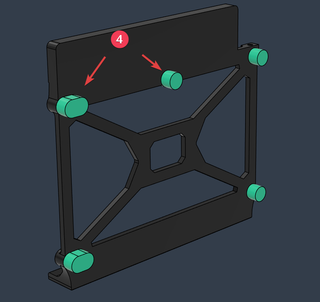
- The following part groups have to be glued together with CA glue
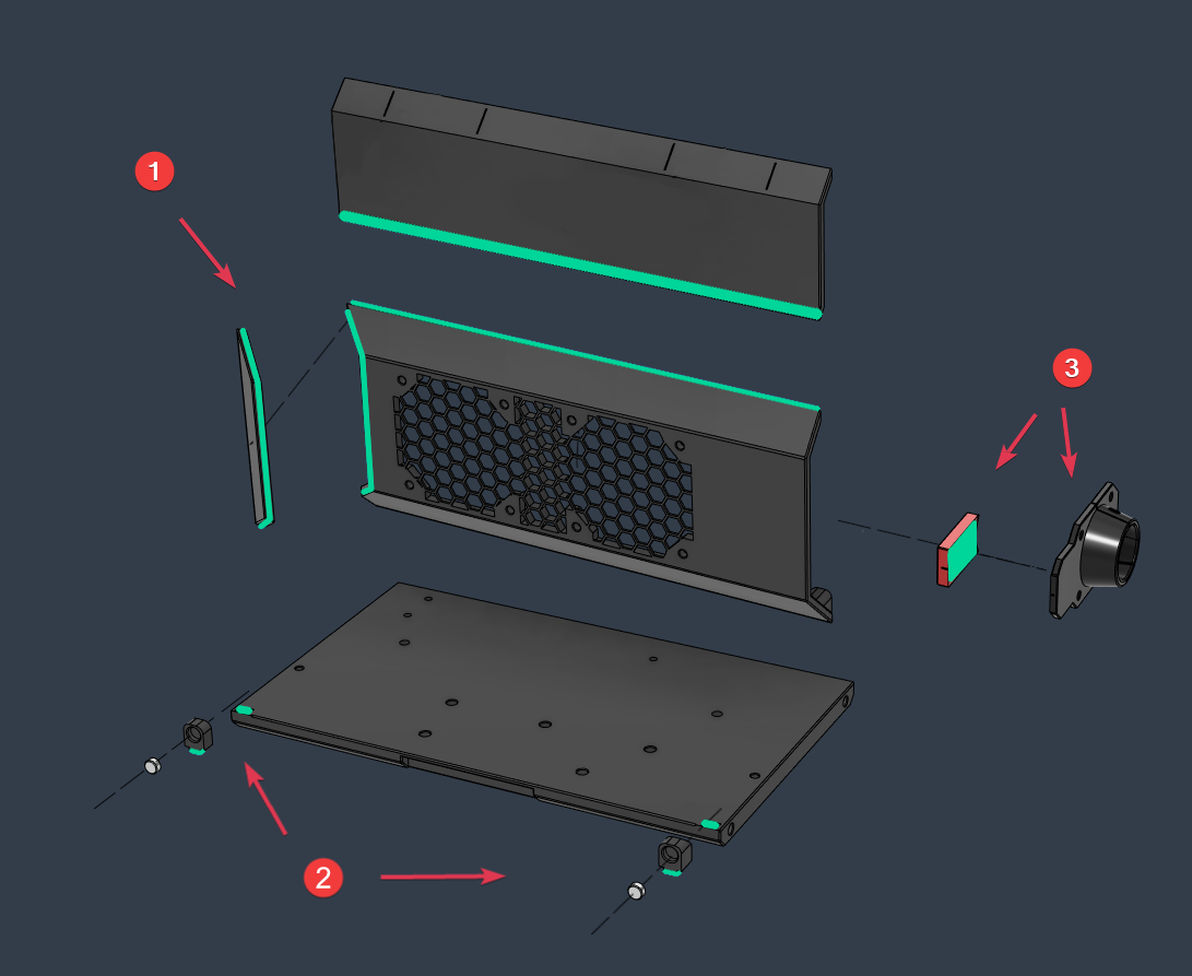
- Glue the support standoffs on the back of the mainboard mount
View Map:
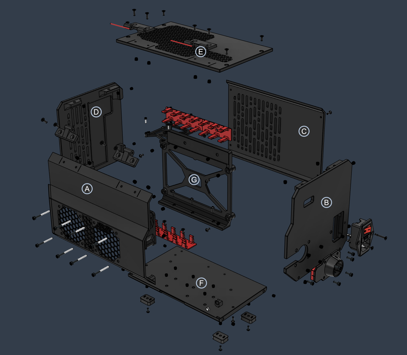
Sections:
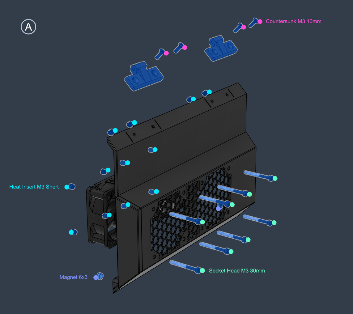
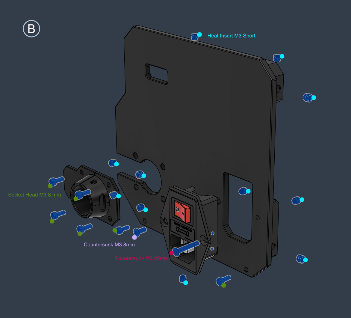
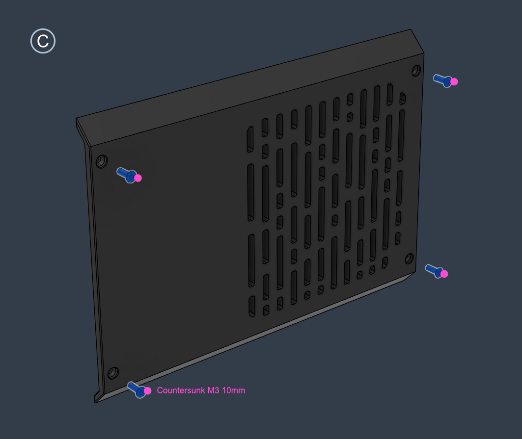
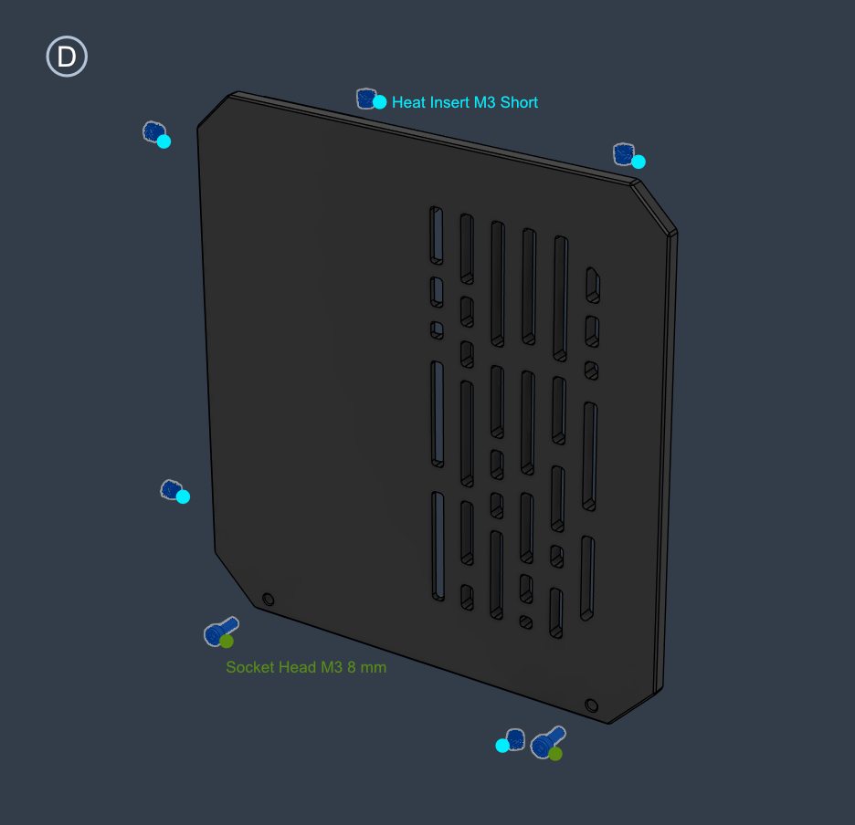
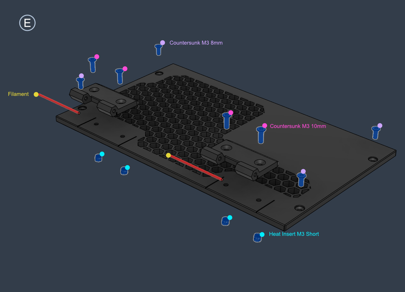
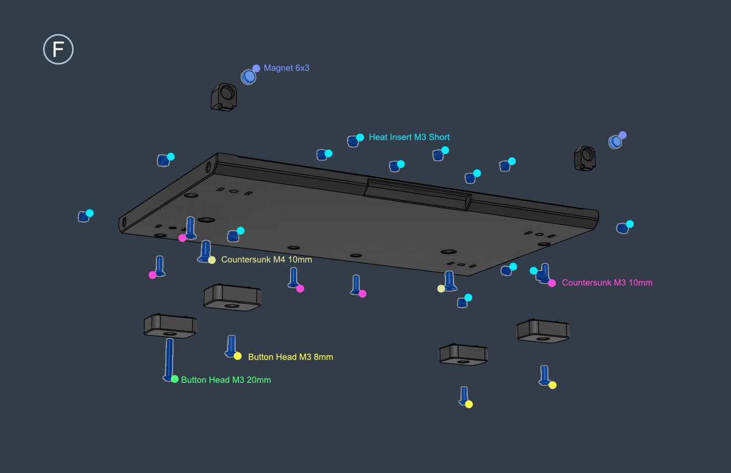
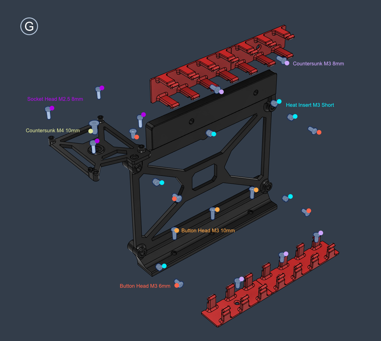
| Cable | Length |
|---|---|
| Ebox Fans | 23 cm |
* To be updated
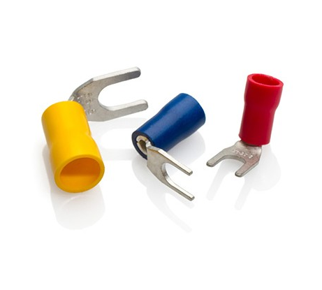
- Due to size constraints, the fork terminals that connect to the main PSU might need to be bent slightly at an angle following the cable direction depending on the type used.
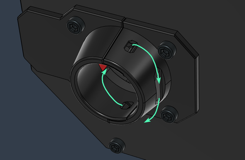
- The main wire loom is secured with a zip tie though the holes in the cable guide
- Please ensure you read the Safety section of this guide.
- Ask for professional help when dealing with AC connections
- Always disconnect the power cable when working on the electronics or opening the box exposing the AC side
- Use the appropriate tools for crimping (check the BOM for recommendations)
- Do not tin wires going into ferrules or fork connectors
- Do not tin or use ferrules for wires going to Wago splice connectors
- Check the tightness of spade connectors (when NOT powered) and inspect the AC socket area from time to time to check for any signs of damage due to arcing or heat. This is a known point of failure that has been observed on other printers in the past
- Crimping Fork Connectors: https://www.youtube.com/watch?v=goxVeefDpQg